Removal of carbon dioxide from air

a technology of carbon dioxide and air, applied in the direction of combustion-air/fuel-air treatment, separation process, filtration separation, etc., can solve the problems of reducing the efficiency of air pressure washing process, consuming significant energy for air pushing through such devices, and comparatively high pressure loss during washing process

Active Publication Date: 2006-08-24
CARBON SINK
View PDF16 Cites 100 Cited by
  • Summary
  • Abstract
  • Description
  • Claims
  • Application Information

AI Technical Summary

Benefits of technology

[0012] The present invention employs as an air/liquid exchange open cell foams. Open-cell foams readily can retain fluids that fill the available foam space. Macroscopic surfaces of the foam block structure are then exposed to the air (or other gas) that is to be brought in contact with the fluid. (Macroscopic surfaces represent the gas-foam interface, these surface structures are large compared to the size of foam cells and define the boundaries of the foam block structure. They delineate the boundary between the inside and the outside of the foam, these surfaces can have complicated topological structures if gas flow channels are designed to cross through the foam.) Flows induced within the open cell structure allow for the continued transport of fluid through the foam's

Problems solved by technology

However, as greenhouse gas concerns mount, CO2 emissions from all sources will have to be curtailed.
Although these methods are efficient in removing CO2, they have a serious disadvantage in that pushing air through such devices consumes significant amounts of energy.
Comparatively high pressure losses occur during these washing processes.
CO2 capture from air is negatively affected by additional energy consumption as this energy consumption usually causes additional CO2 emissions.
Thus, the prior art methods result in the inefficient capture of CO2 from air because these processes heat or cool the air, or change the pressure of the air by substantial amounts.
As a result, the net CO2 captured is reduced by emissions created in the process, or if this CO2 is also captured the overall cost of the process is unnecessarily high.
Furthermore, while scrubber designs for separating CO2 from air already exist, generally they are limited to packed bed type implementations whose goal is typically to remove all traces of an impurity from another gas.
Such a device has the disadvantage that the sorbent material used to separate CO2 from air canno

Method used


Image

  • Removal of carbon dioxide from air
  • Removal of carbon dioxide from air
  • Removal of carbon dioxide from air

Examples


Embodiment Construction

[0027] The present invention is based on the use of an open cell rigid foam as the air / liquid exchanger. Employing open cell rigid foams as the air / liquid exchanges has an advantage in that they not only provide the air / liquid exchange surface, but also the cells become the support structure for the air / liquid interface. Accordingly, the framing or superstructures required for supporting the sheets such as in our aforesaid provisional application may be reduced or eliminated.

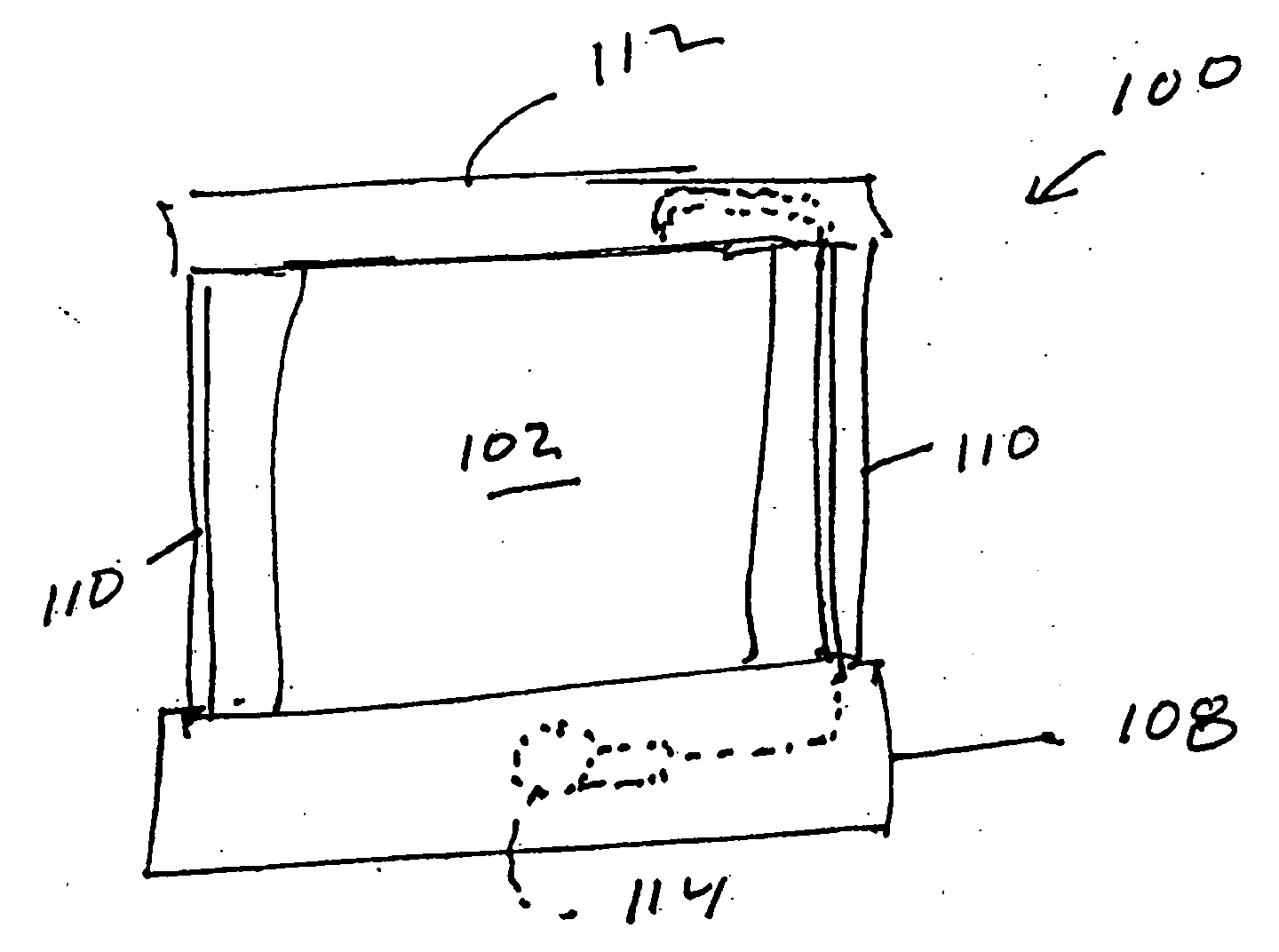
[0028] More particularly, and referring to FIGS. 5-8, an air scrubber unit in accordance with one aspect of the present invention consists of a wind collector 100 comprising a foam block 102 having a plurality of through channels 104 carved through the foam (or molded into the foam) to allow passage of air. Block 102 is mounted within a frame which includes a pan 108, uprights 110 and top 112. Pan 112 serves as a liquid sump for holding a sorbent such as concentrated sodium hydroxide solution. In a preferred em...


PUM

PropertyMeasurementUnit
Pore sizeaaaaaaaaaa
Pore sizeaaaaaaaaaa
Pore sizeaaaaaaaaaa

Abstract

An air/liquid exchanger comprising an open-cell foam 102 supporting a liquid sorbent. The exchanger may be used for removing trace gaseous components from the air.

Description

CROSS-REFERENCE TO RELATED APPLICATIONS [0001] This application claims benefit of U.S. Provisional Application Serial No. 60 / 649,341, filed Feb. 2, 2005, and of U.S. Provisional Application Serial No. 60 / 703,099, filed Jul. 28, 2005.BACKGROUND OF THE INVENTION Description of the Prior Art [0002] The present invention relates to removal of selected gases from air or other gas mixtures. The invention has particular utility for the extraction of carbon dioxide (CO2) from air and will be described in connection with such utilities, although other utilities are contemplated. [0003] Extracting carbon dioxide (CO2) from ambient air would make it possible to use carbon-based fuels and deal with the greenhouse gas emissions of CO2 after they have been released. Since CO2 is neither poisonous nor harmful in parts per million quantities but creates environmental problems simply by accumulating in the atmosphere, it is admissible to remove CO2 from air in order to compensate for an equally size...

Claims


Application Information

Patent Timeline
IPC IPC(8): F02M17/28
CPCB01D53/025B01D53/0415B01D53/06B01D53/14B01D53/18B01D2253/342B01D2257/504B01J20/28014B01J20/28045B01J20/28097F02M35/024F02M35/026Y02C10/06Y02C10/08Y10S55/05Y10S55/42Y02C20/40
Inventor WRIGHT, ALLEN B.LACKNER, KLAUS S.PETERS, EDDY J.
Owner CARBON SINK
Why Eureka
Try Eureka