Structure for stator of reciprocating motor

a technology of stator and reciprocating motor, which is applied in the direction of dynamo-electric machines, mechanical energy handling, magnetic circuit shape/form/construction, etc., can solve the problems of increasing the amount of permanent magnets and increasing production costs

Inactive Publication Date: 2002-09-26
LG ELECTRONICS INC
View PDF8 Cites 18 Cited by
  • Summary
  • Abstract
  • Description
  • Claims
  • Application Information

AI Technical Summary

Benefits of technology

[0125] As so far described, the stator structure of the reciprocating motor of the present invention has the advantages that the flux increased as the motor is overloaded can flow smoothly, so that a core saturation is restrained from occurring, and thus, an efficiency and a reliability of the motor can be heightened.

Problems solved by technology

As an example, as shown in FIG. 3, in case that the outer diameter of the inner core 20 is increased (from D1 to D2), the volume of the armature 40 including the permanent magnet 41 and the outer core 10 is increased, resulting in an increase in the amount of the permanent magnets which would inevitably cause an increase in the production cost.

Method used


Image

  • Structure for stator of reciprocating motor
  • Structure for stator of reciprocating motor
  • Structure for stator of reciprocating motor

Examples


first embodiment

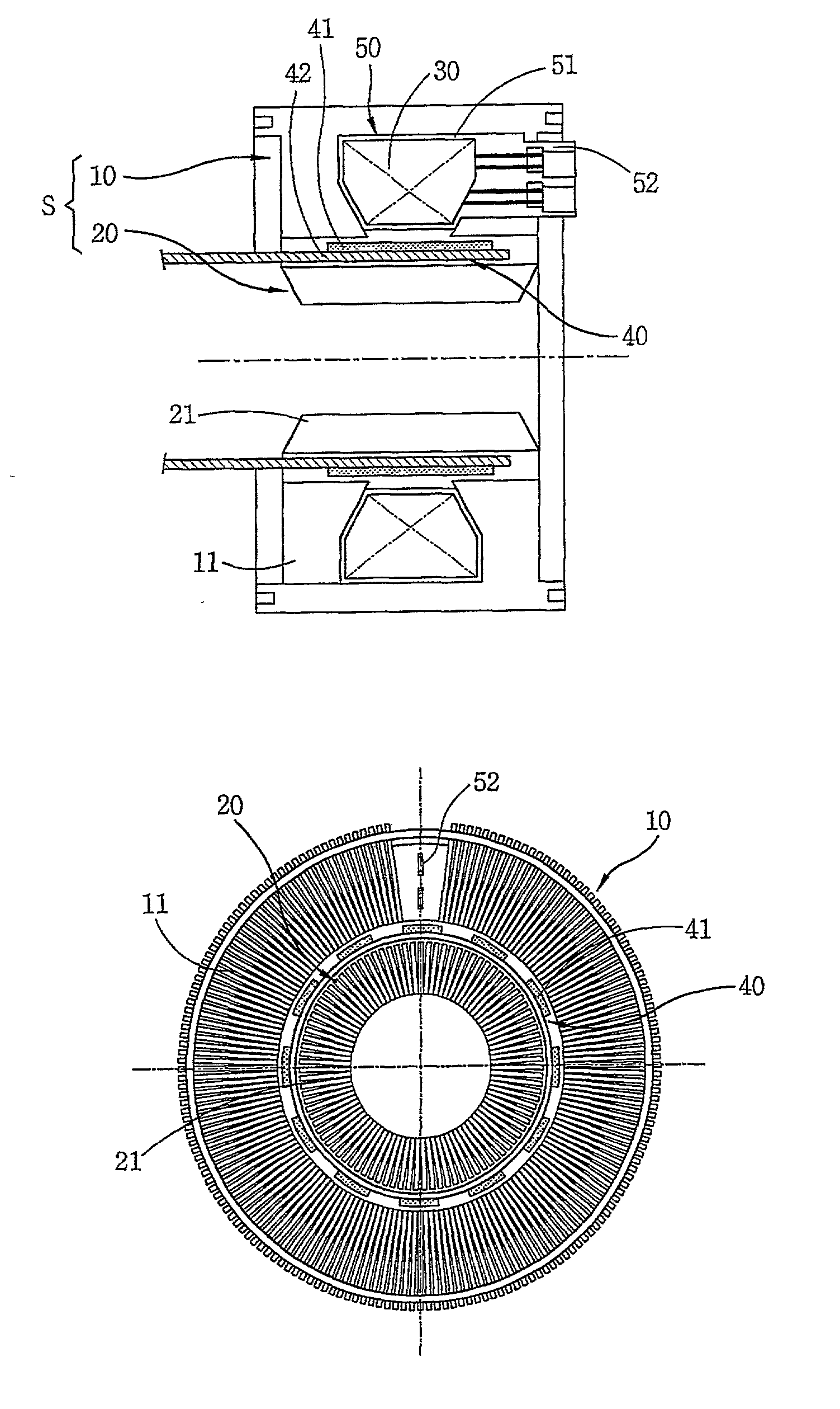
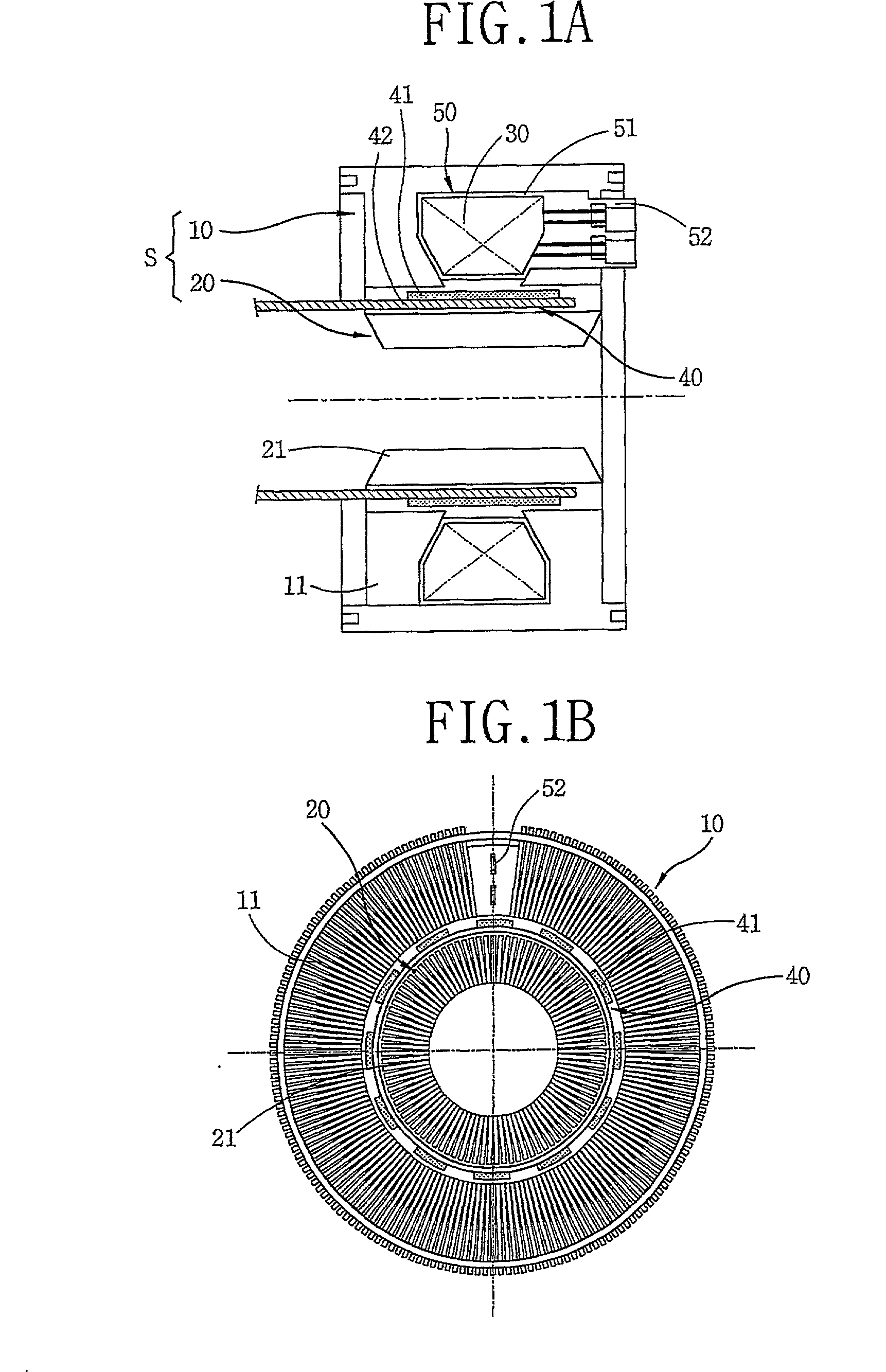
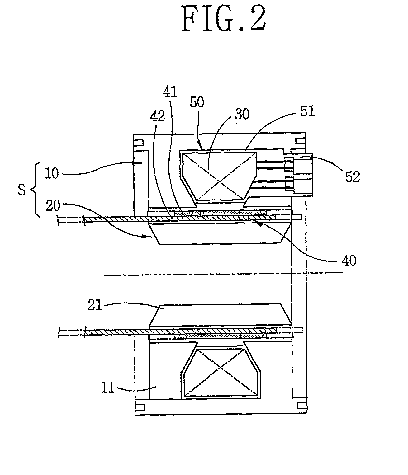
[0047] A stator structure of a reciprocating motor in accordance with the present invention includes a stator (S) having a hollow cylindrical outer core 10 and a hollow cylindrical inner core 60 inserted inside the outer core 10; a winding coil 30 coupled inside the outer core 10; and an armature 40 movably inserted between the outer core 10 and the inner core 60.

[0048] The outer core 10 is formed as a stacked body that a plurality of thin lamination sheets 11 in a predetermined shape are radially stacked to make a hollow cylindrical form.

[0049] The outer core 10 is formed at the outer circumferential face of the bobbin.

[0050] The bobbin 50 includes a coil winding part 51 formed in an annular shape and a terminal part 52 formed at a side of the coil winding part 51.

[0051] The winding coil is constructed that a coil is wound at the coil winding part 51 of the bobbin 50 in a multi-layer, and the wound coil is connected to the terminal part 52.

[0052] The plurality of lamination sheets ...

second embodiment

[0064] The stator structure of the reciprocating motor in accordance with the present invention will now be described.

[0065] FIG. 10 is a front-sectional view of a stator structure of a reciprocating motor in accordance with a second embodiment of the present invention, and FIG. 11 is a side view showing a reciprocating motor core stacking structure of the stator structure of a reciprocating motor in accordance with the second embodiment of the present invention.

[0066] As shown in FIGS. 10 and 11, a reciprocating motor adopting a core stacking structure in accordance with the second embodiment of the present invention includes a stator (S) having a hollow cylindrical outer core 110 and a high density stack-type inner core 160 with a hollow cylindrical form inserted into the outer core 110, a winding coil 30 coupled inside the outer core 110, and an armature 140 having a permanent magnet 141, movably inserted between the outer core 10 and the high density stack-type inner core 160. T...

third embodiment

[0081] The stator structure of the reciprocating motor in accordance with the present invention will now be described with reference to FIGS. 16 and 17.

[0082] FIG. 16 is a front-sectional view of a stator structure of a reciprocating motor in accordance with a third embodiment of the present invention, and FIG. 17 is a side-sectional view of a stator structure of a reciprocating motor in accordance with the third embodiment of the present invention.

[0083] As shown in FIGS. 16 and 17, a reciprocating motor includes a stator (S) having a hollow cylindrical outer core 210 and a composite inner core 260 inserted into the outer core 210 with a predetermined space therebetween; a winding coil coupled inside the outer core 210, and an armature 240 having a permanent magnet 241 and movably inserted between the outer core 210 and the composite inner core 260.

[0084] The outer core 210 is formed such that a plurality of thin lamination sheets 211 in a predetermined form are radially stacked to...


PUM


Abstract

A structure for a stator of a reciprocating motor is capable of heightening an efficiency and a reliability of a motor by maximizing the area of a magnetic path at which a flux flows without increasing the whole volume of a reciprocating motor so that the flux, which is to be increased as an overload works on the motor, flows smoothly to thereby restrain generation of a core saturation. The stator structure includes a stator having a hollow cylindrical outer core and an inner core inserted into the outer core and formed as a plurality of mutually coupled hollow cylindrical stacked bodies and a winding coil connected into the outer core and an armature having a permanent magnet attached at one side thereof and movably inserted between the outer core and the inner core.

Description

[0001] The present invention relates a stator structure of a reciprocating motor, and more particularly, to a stator structure a reciprocating motor in which an area of a magnetic path is enlarged by increasing an area of an inner core where flux flows.[0002] A general reciprocating motor has a plane form of magnetic flux compared to a general motor which has a cubic structure of magnetic flux. A flat armature is linearly moved on a plane according to variation of the magnetic flux formed on a fixing part.[0003] FIGS. 1A and 1B show an example of the reciprocating motor which includes a stator (S) having a hollow cylindrical outer core 10 and a hollow cylindrical inner core 20 inserted into the outer core 10, a winding coil 30 coupled inside the outer core 10, and an armature 40 having a permanent magnet 41 and movably inserted between the outer core 10 and the inner core 20.[0004] In the conventional reciprocating motor constructed as described above, when a current flows to the wi...

Claims


Application Information

Patent Timeline
Patent Type & Authority Applications(United States)
IPC IPC(8): H02K1/18H02K1/12H02K33/16
CPCH02K1/12H02K33/16
Inventor SONG, GYU-YOUNGPARK, JUNG-SIKLEE, HYUKKIM, HYOUNG JINHUR, KYUNG BUMHONO, EON PYO
Owner LG ELECTRONICS INC
Why Eureka
Try Eureka