Vehicle with a super-capacitor for recovery of energy on braking

a supercapacitor and braking technology, applied in the direction of motor/generator/converter stopper, vehicle sub-unit features, dynamo-electric converter control, etc., can solve the problems of increasing the mass of the device compared with the amount of electrical energy stored, presenting various problems, and increasing the mass of the vehicl

Inactive Publication Date: 2002-10-03
CONCEPTION & DEV MICHELIN SA
View PDF4 Cites 44 Cited by
  • Summary
  • Abstract
  • Description
  • Claims
  • Application Information

AI Technical Summary

Problems solved by technology

However, the use of electric accumulators presents various problems.
Such a device has a high mass compared with the amount of electrical energy stored.
This considerably increases the mass of a vehicle.
It is also a source of a waste of energy during acceleration, and even during braking, since the efficiency of the conversions of kinetic energy into electrical energy and of electrical energy into kinetic energy cannot be 100%.
Furthermore, the problems with the dynamic behavior of a vehicle are all the more crucial if the vehicle is heavy.
In addition, the known batteries do not accept sufficiently intense recharging currents to be able to rapidly recover a lot of braking energy.
Of course, the lower the efficiencies in the energy conversions, the less is recovered on braking of the energy which has had to be expended to accelerate this excess mass due to the batteries.
The problem which arises, therefore, to be able to recover and store sufficient energy to improve the overall efficiency significantly, that is to say, to reduce the fuel consumption for a given duty.
But, in this case, the periods during which the vehicle has to be restrained or decelerated are extremely long and if it is desired to recover the energy during all of these phases, it is necessary to use considerable storage capacities.
The weights of the storage systems installed in the vehicle could become prohibitive, whatever the technology used for these systems.

Method used


Image

  • Vehicle with a super-capacitor for recovery of energy on braking
  • Vehicle with a super-capacitor for recovery of energy on braking
  • Vehicle with a super-capacitor for recovery of energy on braking

Examples


Embodiment Construction

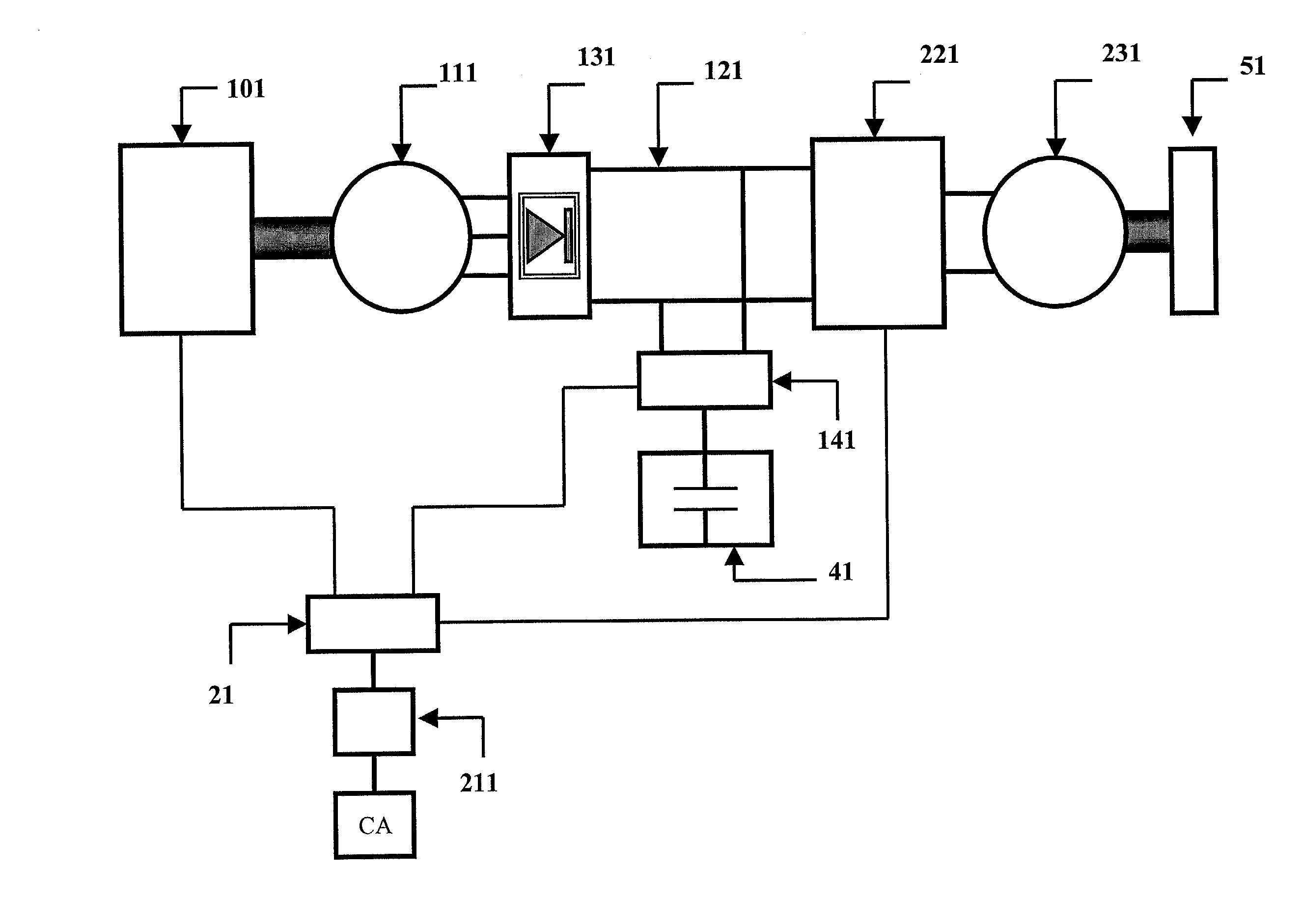
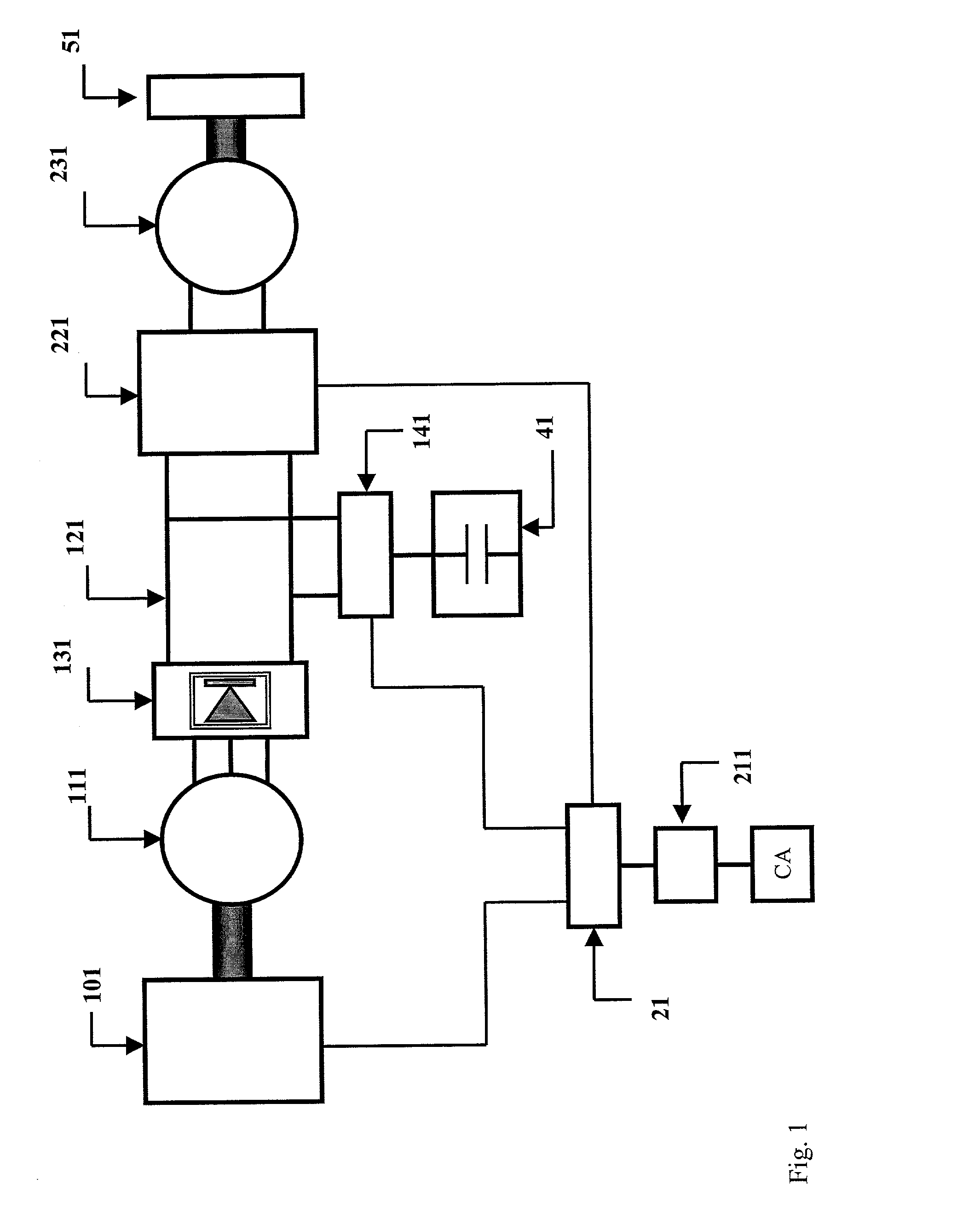
[0031] In FIG. 1, there can be seen an engine 101 driving an alternator 111. The electrical energy supplied by the latter feeds an electric traction motor 231, via a rectifier 131, an electric line 121, and an inverter 221. It should be mentioned, in passing, that in the case of a vehicle with a fuel cell, the electrical energy generating system replaces the elements 101, 111 and 131 of FIG. 1.

[0032] The electric traction motor 231 is mechanically coupled to a wheel 51. A super-capacitor 41 is connected to the electric line 121, by means of a device 141 for managing the operating mode. There are two operating modes: the energy "recovery" mode and the energy "restoration" mode. The assembly consisting of super-capacitor 41 and management device 141 is connected in parallel with the assembly consisting of electric traction motor 231 and inverter 221.

[0033] A unit 21 for controlling the torque applied to the vehicle wheel manages the circulation of the electrical energy in the drivetra...


PUM


Abstract

A vehicle has an engine driving an alternator. The electrical energy supplied by the alternator feeds an electric traction motor, via a rectifier, an electric line, and an inverter. The electric traction motor is mechanically coupled to a wheel. A super-capacitor is connected to the electric line by means of a voltage-matching circuit. A unit for controlling the torque applied to the vehicle wheel manages the circulation of the electrical energy in the drivetrain so as always to discharge the super-capacitor as a priority, in order to be able to be ready to recover the energy at the next braking.

Description

[0001] 1. Technical Field of the Invention[0002] The present invention relates to road motor vehicles using electricity for their propulsion.[0003] 2. The Related Art[0004] For example, series hybrid vehicles and parallel hybrid vehicles are known. In vehicles with a so-called series hybrid drivetrain, an engine drives an alternator which converts the mechanical energy available at the shaft of the engine into electrical energy. This electrical energy supplies one or more electric traction motors mechanically connected to the driving wheels of the vehicle. The engine is not mechanically connected to the wheels. In vehicles with a so-called parallel hybrid drivetrain, an engine and an electric motor are both mechanically connected to the driving wheels; the torques which they deliver can be added together to drive the driving wheels.[0005] In both cases, it is well known to install electric accumulators, especially where it is desired to be able to drive the vehicle in purely an elec...

Claims


Application Information

Patent Timeline
Patent Type & Authority Applications(United States)
IPC IPC(8): B60K6/28B60L11/18B60K6/46B60K6/48B60L50/15B60L50/16B60W10/08B60W10/26B60W20/00H02P3/18
CPCB60K6/28B60Y2400/114B60K6/48B60L7/14B60L11/005B60L11/123B60L11/14B60W10/08B60W10/26B60W20/00B60W2510/244Y02T10/6217Y02T10/6221Y02T10/7022Y02T10/7077Y02T10/92B60K6/46B60L50/40B60L50/61B60L50/16Y02T10/62Y02T10/70Y02T10/7072B60W20/10
Inventor CHARAUDEAU, JEAN-JACQUESBOURQUI, GERALDVARENNE, PIERRE
Owner CONCEPTION & DEV MICHELIN SA
Why Eureka
Try Eureka