Data switch and a method for controlling the data switch

a data switch and switch technology, applied in data switching networks, store-and-forward switching systems, multiplex communication, etc., can solve the problems of uncontrollable switch congestion and unbounded cell latencies,

Active Publication Date: 2002-10-03
MICRON TECH INC
View PDF7 Cites 34 Cited by
  • Summary
  • Abstract
  • Description
  • Claims
  • Application Information

AI Technical Summary

Benefits of technology

[0008] The invention thus makes it possible to reduce, or even eliminate, variation in the latency of the throughput of time division multiplexed traffic.
[0013] The TDM traffic may thus be arranged to be inherently free of congestion. Any congestion is resolved by the higher level connection establishment processes. The present invention makes it possible to establish connections in such a way that cells can always be forwarded without any queuing or arbitration. This feature is potentially of great value, since a prime requirement for a switch matrix handling TDM traffic is to present a low, clearly defined latency to TDM cells.

Problems solved by technology

For such cells, the degree of congestion in the switch cannot be controlled, and hence the cell latencies are inevitably unbounded.

Method used


Image

  • Data switch and a method for controlling the data switch
  • Data switch and a method for controlling the data switch
  • Data switch and a method for controlling the data switch

Examples


Embodiment Construction

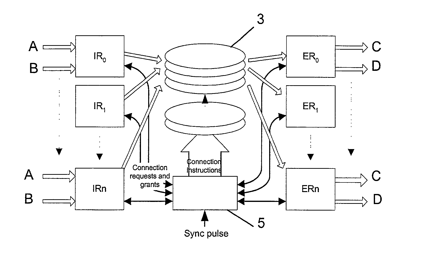
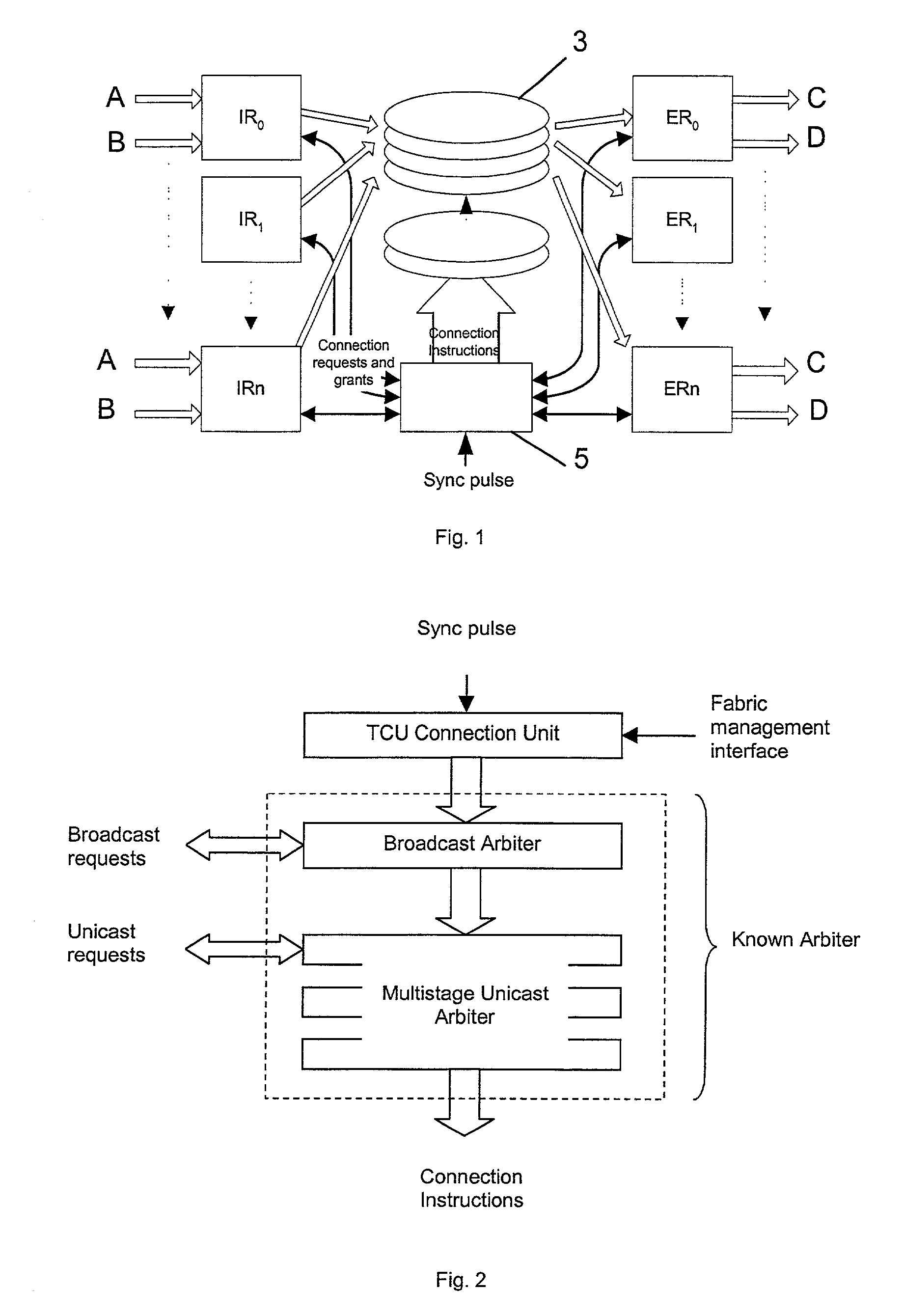
[0025] FIG. 1 shows an embodiment of a switch according to the present invention. The switch includes n+1 ingress routers (where n is a positive integer, such as 31) labelled IR.sub.0 to IR.sub.n, and an equal number n+1 of egress routers labelled ER.sub.0 to ER.sub.n. The ingress routers and egress routers are connected by a switching matrix 3 which is capable of connecting any set of ingress routers to any set of egress routers. The switch is controlled by a control unit 5, which defines the connections the switching matrix 3 makes, by generating connection instructions and transmitting them to the switching matrix 3.

[0026] Each of the ingress routers IR.sub.0 to IR.sub.n receives data from two input buses, labelled A and B. Input bus A, which may be a conventional CSIX or Intel IXBus, transmits data cells to the corresponding ingress router at times which are not predefined. The ingress router is provided with VOQs for each of the egress routers ER.sub.0 to ER.sub.n and priority ...


PUM


Abstract

A data switch is proposed of the type having virtual queue ingress routers interconnected with egress routers by way of a memoryless switching matrix controlled by a control unit which performs an arbitration process to schedule connections across the switch. This scheduling is performed to ensure that data cells which arrive at the ingress routers at unpredictable times are transmitted to the correct egress routers. Each ingress router further includes a queue for time division multiplex traffic, and at times when such traffic exists, the control unit overrides the arbitration process to allow the time division multiplex traffic to be transmitted through the switch.

Description

[0001] The present invention relates to methods for controlling a data switch which passes data, including time division multiplexed data, selectively between a plurality of data input ports and a plurality of data output ports. The invention further relates to such a switch.DESCRIPTION OF THE PRIOR ART[0002] Our patent applications PCT / GB99 / 03748 and PCT / GB99 / 00405 (respectively published as WO 00 / 038375 and WO 99 / 43131, the disclosures of which are incorporated herein by reference in their entirety) show data switches which comprise a plurality of input ports, which are operated by respective ingress routers, and a plurality of output ports, which are operated by respective egress routers. The input and output ports are interconnected by a switching matrix under the control of a control unit. The switching matrix can form connections between selected ones of the input and output ports. Cells of incoming data arrive at one of the input ports for transmission to one of the output po...

Claims


Application Information

Patent Timeline
Patent Type & Authority Applications(United States)
IPC IPC(8): H04L12/54H04L12/64H04L12/70H04L12/931H04L12/933
CPCH04L12/5601H04L12/6418H04L49/106H04L2012/6413H04L49/606H04L2012/5679H04L2012/5681H04L49/203
Inventor PIEKARSKI, MAREK STEPHENHOWARTH, PAUL GRAHAMTCHAPDA, YVES
Owner MICRON TECH INC
Why Eureka
Try Eureka