High-dispersion fibers for high-speed transmission

a high-dispersion fiber and high-speed technology, applied in multiplex communication, cladded optical fibers, instruments, etc., can solve the problems that the use of fibers with dispersion values of more than 20 ps/(nm-km) would not be considered suitable for high-speed systems based on conventional design principles, and achieves improved system performance, lower distortion of fibers, and higher dispersion values.

Inactive Publication Date: 2002-10-03
WSOU INVESTMENTS LLC
View PDF0 Cites 2 Cited by
  • Summary
  • Abstract
  • Description
  • Claims
  • Application Information

AI Technical Summary

Benefits of technology

0006] We have discovered that inherent fiber dispersion affects signals transmitted in the pseudo-linear regime in a manner completely different than signals transmitted by conventional techniques. Surprisingly, using the pseudo-linear regime, optical pulses actually transmit with lower distortion in fibers with higher dispersion values. Use of fibers with dispersion values of more than 20 ps/(nm-km) would not be considered suitable for high-speed systems based on conventional design principles. However, we have found for instance that fiber with a dispersion value higher than 20 ps/(nm-...

Problems solved by technology

Use of fibers with dispersion values of more than 20 ps/(nm-km) would not be ...

Method used


Image

  • High-dispersion fibers for high-speed transmission
  • High-dispersion fibers for high-speed transmission
  • High-dispersion fibers for high-speed transmission

Examples


Embodiment Construction

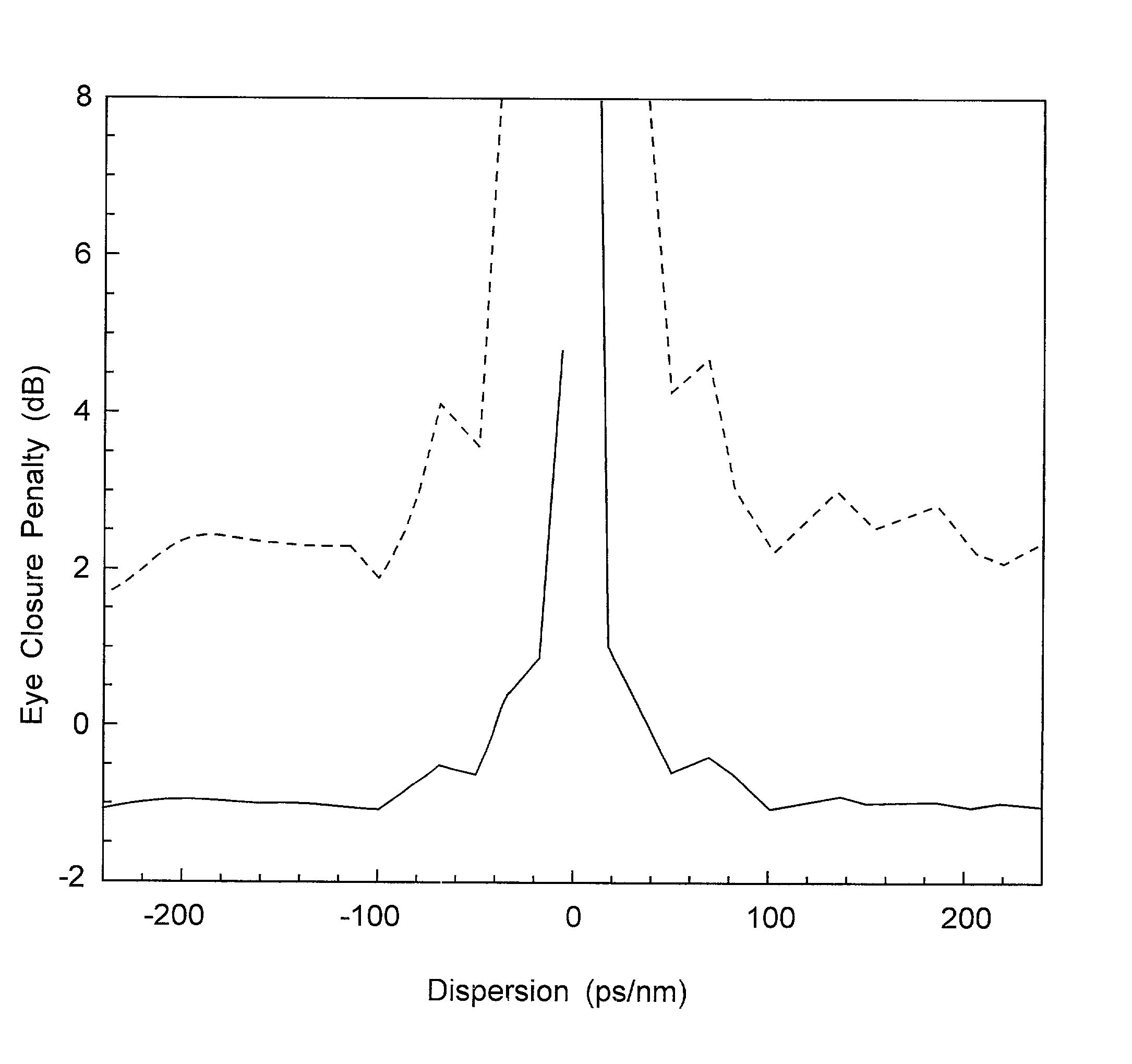
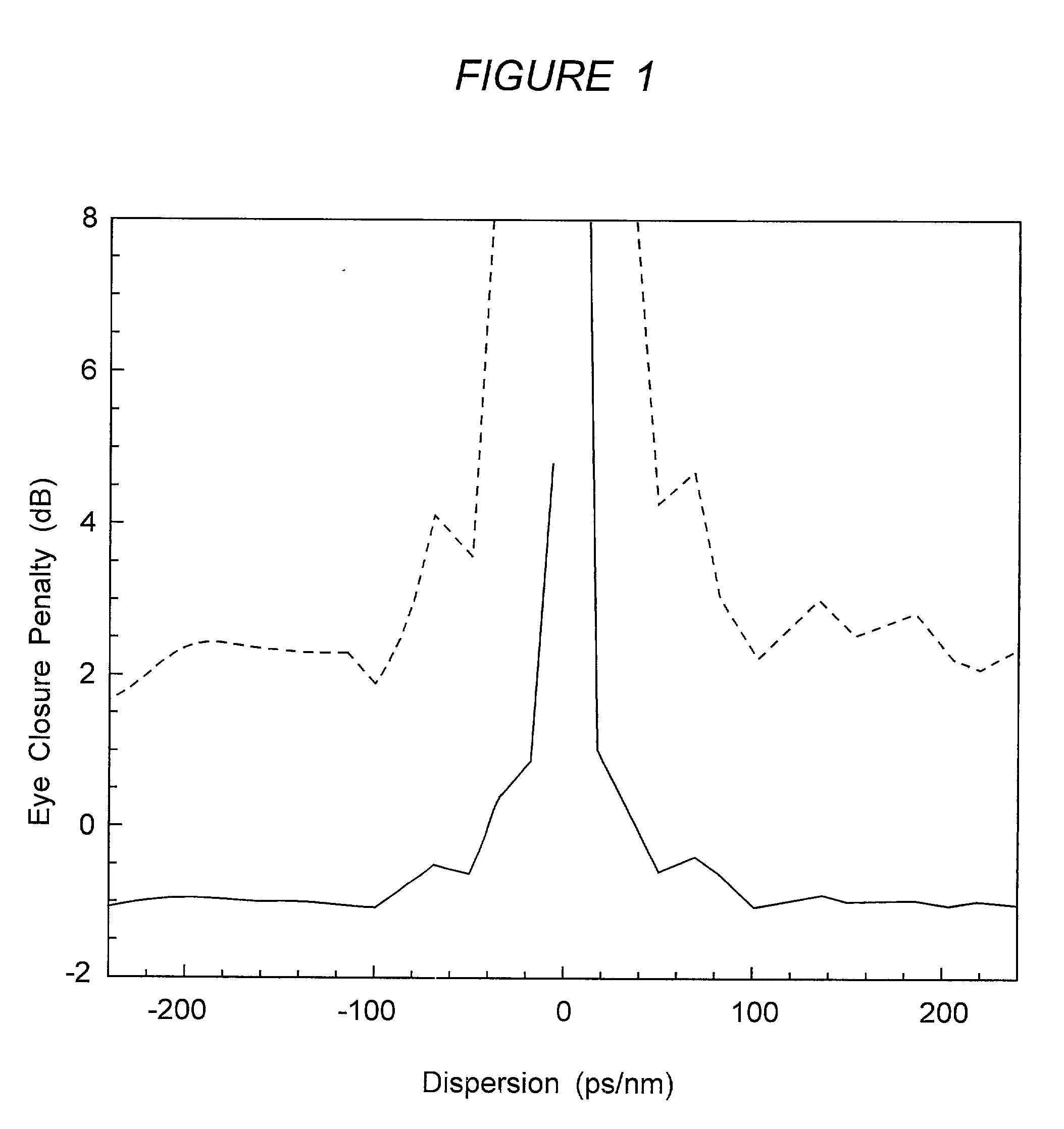
[0028] To demonstrate the principles of the invention, simulated measurements were made of pulse transmission in fibers with a number of different dispersion values. These provided plot points that are plotted in FIG. 1. The characteristic measured was the eye closure penalty in dB, a standard indicator of the pulse degradation due to non-linear and dispersion effects in the fiber. The fiber length used was 80 km, the wavelength was 1.55 .mu.m, and the bit rate was 160 Gb / s. Data was generated for two duty cycles, 20% and 33%. Data for the 20% duty cycle is represented by the solid curve and data for the 33% duty cycle is represented by the dashed curve. The corresponding pulse duration was 1.25 ps and 2.1 ps respectively. These pulse durations are low in comparison to those recommended above, and reflect the change in pulse specifications as the bit rate increases by 4.times.. However, the duty cycles of 20% and 33% are typical for PLMT. Results for a 40 Gb / s system operating with ...


PUM


Abstract

The specification describes an optical transmission system for high speed, high capacity digital pulse transmission, i.e. at least 10 Gb/s at a duty cycle of at least 10%, which uses transmission fiber with a dispersion value greater than 20 ps/(nm-km) or more negative than -5 ps/(nm-km). The system operates in the pseudo-linear transmission mode (PLTM). In the PLTM it was discovered that pulse distortion decreases, i.e. eye closure penalty actually decreases, as the dispersion value increases. System performance actually improves by increasing the value of absolute dispersion of the transmission fiber.

Description

[0001] This invention relates to fiber-optic communications systems, and more particularly to prescription on the range of values of fiber dispersion for the design of systems operating with high-speed, high-power transmission.[0002] With the advent of optical amplifiers which can compensate for fiber loss, the reach of fiber-optic communication systems at 10 Gb / s per channel and beyond, is limited largely by chromatic dispersion. Chromatic dispersion causes different parts of the signal spectrum to arrive at the distant end of the system at different times. An optical signal carrying information has a finite bandwidth (spread in wavelengths). If these wavelengths propagate at different velocities along the fiber, the pulses will be dispersed. The dominant cause of chromatic dispersion is material dispersion, the variation in the refractive index versus wavelength of silica, the basic material from which all low loss transmission fibers are made. However, the chromatic dispersion of...

Claims


Application Information

Patent Timeline
IPC IPC(8): H04B10/00H04B10/02H04B10/18G02B6/02H04J14/00H04J14/02
CPCH04B10/2525
Inventor ESSIAMBRE, RENE-JEANMIKKELSEN, BENNY
Owner WSOU INVESTMENTS LLC
Why Eureka
Try Eureka