Process of bending laminated metal sheet

a technology of laminated metal and bending process, which is applied in the field of shaping or bending laminated metal webs or blanks, can solve the problems of unreliable or even unacceptable, unreliable sheet metal stamping or progressive die press, and unexpectedly difficult sheet metal shaping or bending, so as to eliminate the sliding of laminate sheets, reduce the thickness of sheets

Inactive Publication Date: 2002-10-17
BUHRKE IND
View PDF0 Cites 7 Cited by
  • Summary
  • Abstract
  • Description
  • Claims
  • Application Information

AI Technical Summary

Benefits of technology

0011] A more detailed feature of this invention is to deform the laminated metal web or blank by depressing its opposite faces at locations essentially opposite one another, to reduce the sheet thickness greatest at what should be the center of the anticipated corner to be formed. This might be done at one press station with the web or blank generally planar by opposed press tools, each having a convex or rounded working edge elongated along the length of the intended corner, striking against the opposite sheet faces.
0012] A suitable forming press tool might have a convex protrusion having a curvature radius between being approximately equal to and several times the original sheet thickness; and each face might be depressed between possibly 10-35% of the original sheet thickness, leaving the thinnest part of the web possibly between 80-30% of the original sheet thickness. The convex shape of the cooperating tools and the extent of the concave deformations provide that the greatest sheet depression occurs across opposed arcuate curvatures, although minor bulges might occur above the face of the blank immediately adjacent the ends of each depressed region, and further seem to confine all blank bending in these regions and virtually eliminates laminate sheet sliding or shifting in the blank regions laterally adjacent the depressions.

Problems solved by technology

While the laminated metal housing and / or piece part made therefrom will effectively reduce noise or vibration transmission, the shaping or bending of the laminated metal, from a flat piece, to the desired three dimensional housing or any other intended part shape, by a conventional sheet metal stamping or progressive die press has been unexpectedly difficult, unreliable or even unacceptable.
Such sheet shifting could raise cosmetic concerns at visible misaligned sheet edges, and / or could create functional tolerance problems of location and / or size of holes, for example, due to misaligned sheet edges at the holes previously punched through the sheets.
Further, sheet separation has been experienced at the edges, and / or internal stresses created in the laminated sheets on both sides of the formed corner has bowed or otherwise distorted the panels from being planar, as intended.

Method used


Image

  • Process of bending laminated metal sheet
  • Process of bending laminated metal sheet

Examples


Embodiment Construction

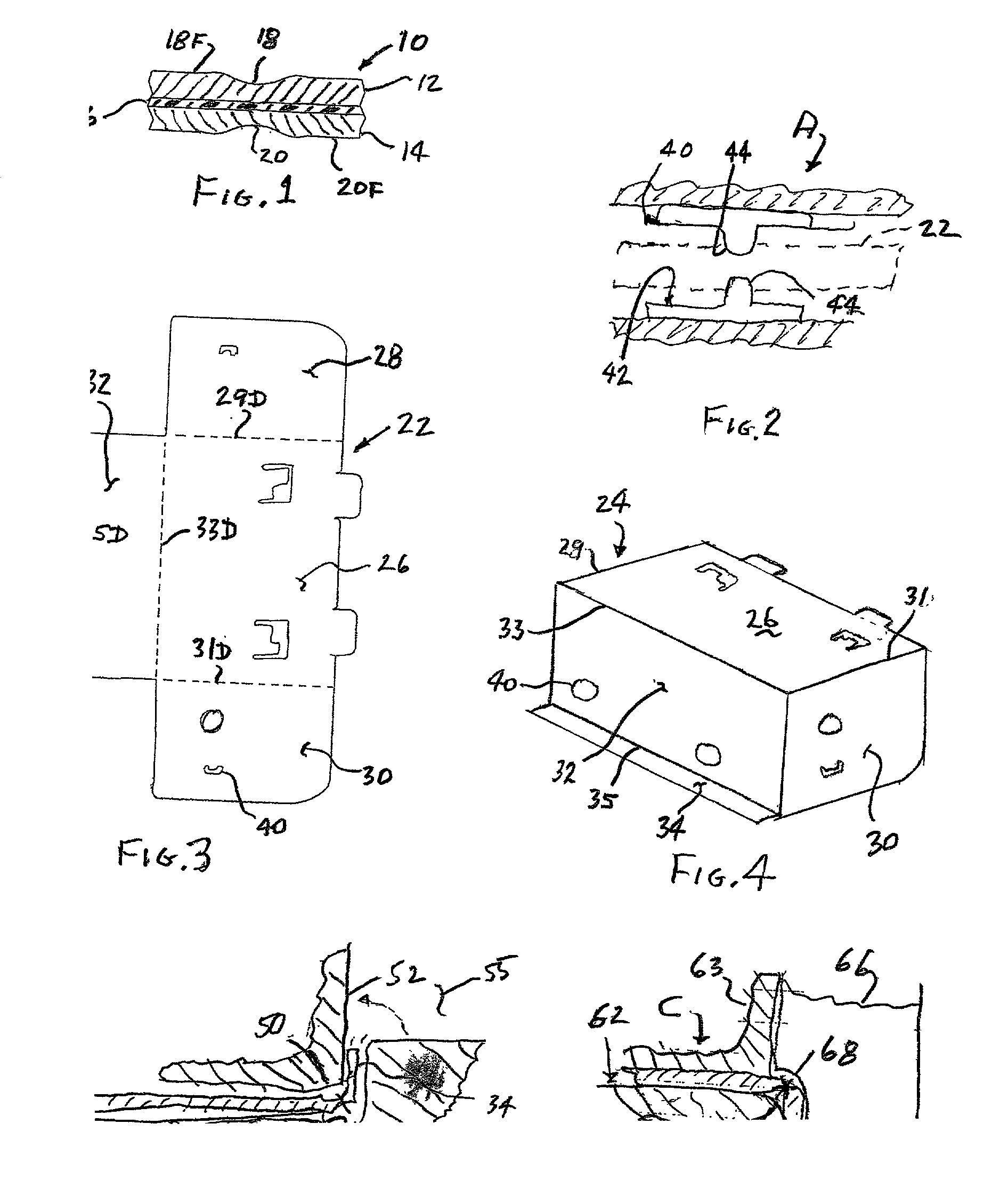
[0019] FIG. 1 shows a sectional view of a piece 10 of laminated metal, being comprised of two metal sheets 12, 14 that sandwich and are held separated but relative to one another by a core 16 of a bonding elastic or vicoelastic material. The figure also shows typical crease regions or depressions 18, 20 formed in the opposite faces 18F, 20F of the laminated metal piece, according to the teachings of this invention.

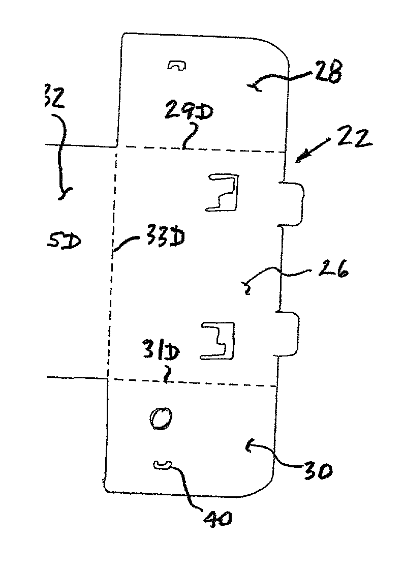
[0020] More specifically, FIG. 3 shows in plan view a blank 22 which might be folded to three-dimensional piece-part 24 illustrated in FIG. 4. The piece part 24 has main panel 26, and opposed side panels 28, 30 (30 being shown only in FIG. 4), and side panel 32 folded 90 degrees from the main panel across corners 29, 31, 33 respectively; and further has flange panel 34 folded 90 degrees from the side panel 32 across corner 35.

[0021] The invention provides that prior to bending the fold panels 28, 30, 32, 34 relative to its adjacent hinged panel, crease regions or depressio...


PUM

PropertyMeasurementUnit
thicknessaaaaaaaaaa
thicknessaaaaaaaaaa
thicknessaaaaaaaaaa

Abstract

This invention improves on the process of bending in a conventional progressive stamping press a flat laminated metal sheet around a corner edge of a die block to form a generally straight piece-part corner, and comprises the steps of forming extended concavely rounded depressions in the opposite sheet faces at the sheet locations of the intended corner, then locating and clamping the sheet with the depressed regions aligned along a die block corner, and then mechanically bending the sheet with said depressed sheet regions aligned over the die block corner edge. The sheet depressions can be aligned essentially opposite one another, being rounded concavely and of a high width-to-depth ratio and of a depth to reduce the sheet to between 80-30% of its original thickness. The sheet depressions might occur at one stamping press station by opposing press tools each having a convex rounded working edge elongated along the length of the intended corner, with the blank bending occurring at a subsequent stamping press station.

Description

[0001] It has long been common to enclose physical components, such as electrical or electronics controls, mechanical pumps, valving, cooling fans and powering electric motors, or the Like, in a formed sheet metal housing having rigidity and strength for protecting the enclosed components. Use of conventional progressive stamping presses has been a favored manner of fabricating three-dimensional metal parts including housings, particularly when a great number of pieces are to be made, as a continuous web or blank of material can be used in making up all or a major portion of the part, for reducing inventory and the time and effort of assembling different parts. Progressive fabricating operations will be performed at sequential stamping stations, such as for shaping ribs, bosses, etc. on the blank surfaces, and / or for cutting, shearing or piercing through the blank for yielding needed holes or the overall blank shape, and / or for folding the blank to a general three dimensional part s...

Claims


Application Information

Patent Timeline
Patent Type & Authority Applications(United States)
IPC IPC(8): B21D5/00B21D35/00
CPCB21D35/00B21D5/00
Inventor MCKINNEY, JOHN L.KRUTZ, KEITH J.
Owner BUHRKE IND
Why Eureka
Try Eureka