
Accelerator pedal device

a technology of accelerator pedal and accelerator shaft, which is applied in the direction of mechanical control devices, process and machine control, instruments, etc., can solve the problems of increasing the load applied to the shaft of the accelerator pedal arm, giving discomfort to the driver in the return of the accelerator pedal, etc., to prevent the generation of discomfort and prevent excessively large loads

Inactive Publication Date: 2002-10-24
AISIN SEIKI KK +1
View PDF29 Cites 55 Cited by
  • Summary
  • Abstract
  • Description
  • Claims
  • Application Information

AI Technical Summary

Benefits of technology

[0008] It is an object of the present invention to provide an accelerator pedal device which can considerably prevent the generation of discomfort in the accelerator manipulation and, at the same time, can prevent an excessively large load from being applied to an accelerator pedal shaft.
[0010] The manner of operation of the accelerator pedal device is explained with respect to a case in which the accelerator pedal arm is manipulated by an accelerator pedal mounted on the accelerator pedal arm. When an accelerator manipulator steps on the accelerator pedal so as to tilt the accelerator pedal arm in a predetermined direction, the resilient member which is interposed between a given portion of the accelerator pedal arm and a given position of a hysteresis lever is contracted or elongated so that a reaction force which faces an accelerator manipulating force (a so-called pedal reaction force) and a hysteresis load are generated. Accordingly, the accelerator manipulator can have a reasonable moderation feeling at the time of acceleration and can maintain the accelerator pedal at a fixed position with a manipulation force smaller than a manipulation force necessary at the time of stepping-in the accelerator pedal when the accelerator pedal is to be maintained at the fixed position.
[0011] According to the accelerator pedal device, the resilient member is interposed between the accelerator pedal arm and the hysteresis lever which are arranged to cross each other. The interposed resilient member prevents an excessively large load from being applied to a pivoting portion of the accelerator pedal arm.
[0012] According to the accelerator pedal device, the resilient member which generates a reaction force (pedal reaction force) against an accelerator manipulating force and the resilient member which generates a hysteresis load are formed of the same member. Accordingly, even if a malfunction occurs with respect to the operation of the resilient member, both of the pedal reaction force and the hysteresis load which act in the directions opposite to each other can be cancelled or decreased so that large discomfort in the return of the accelerator pedal hardly occurs as much as possible.

Problems solved by technology

The first problem is that, since the pedal reaction force spring and the hysteresis spring are formed as separate members, even if a malfunction occurs with respect to the operation of the pedal reaction force spring, only the hysteresis load remains, which results in giving discomfort to a driver in the return of the accelerator pedal.
The second problem is that, since the hysteresis generating member and the like are arranged only at one side of the accelerator pedal arm, it is feared that the load applied to an shaft of the accelerator pedal arm increases.

Method used


Image

  • Accelerator pedal device
  • Accelerator pedal device
  • Accelerator pedal device

Examples


Embodiment Construction

[0016] The present invention will be described with reference to the accompanying drawings.

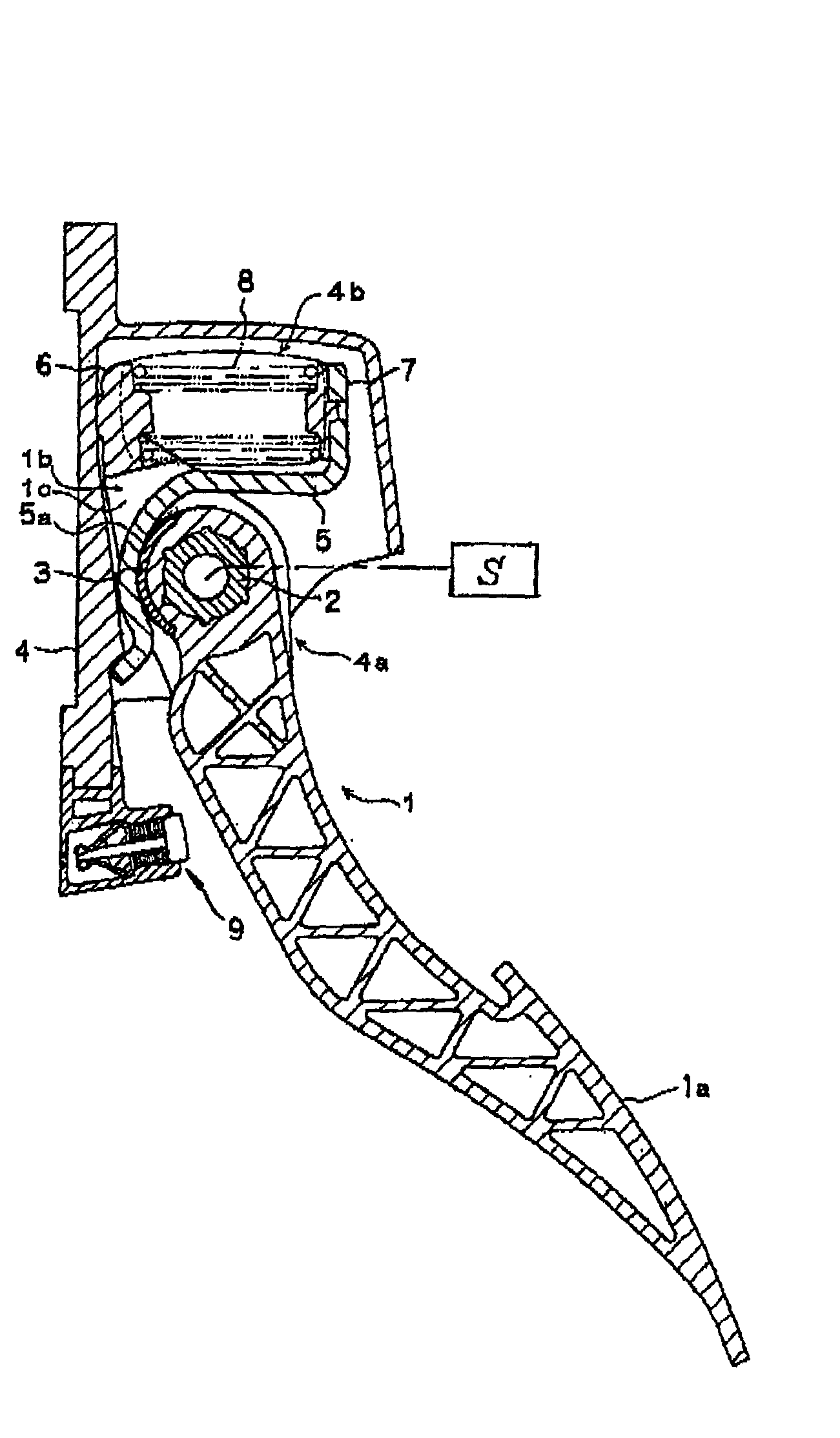
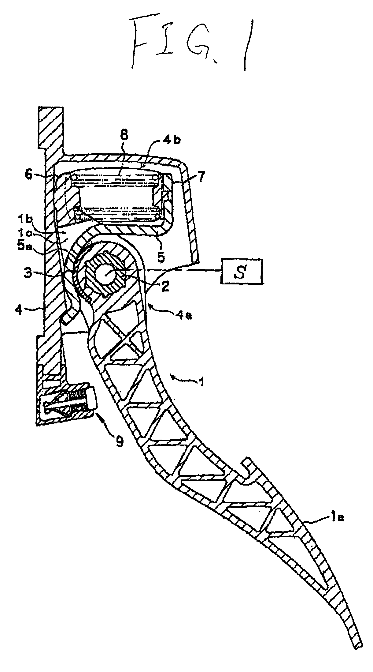
[0017] FIG. 1 is an explanatory view of an accelerator pedal device according to one embodiment of the present invention. Referring now to FIG. 1, an accelerator pedal arm shaft 2 is pivotally and rotatably mounted on a housing 4. A pivoting portion (boss portion) of an accelerator pedal arm 1 is brought into spline engagement with an outer peripheral portion of the accelerator pedal arm shaft 2. Due to such a constitution, the accelerator pedal arm 1 is pivotally mounted on the housing 4 and tilted by the accelerator manipulation. Further, an accelerator pedal la is formed on one end of the accelerator pedal arm shaft 2. A liner 3 is provided or formed on a portion of the accelerator pedal arm 1 which is disposed in the vicinity of a pivoting point of the accelerator pedal arm 1 (in the vicinity of the accelerator pedal arm shaft 2). The accelerator pedal arm 1 includes an arm portion 1c exte...


PUM


Abstract

An accelerator pedal device includes a pedal arm, a liner, a hysteresis lever, and a spring. The pedal arm is pivotally supported on a housing and tilted by accelerator manipulation. The liner is formed on the pedal arm in the vicinity of a pivoting point of the pedal arm. The resilient hysteresis lever is engaged with the housing to cross the pedal arm. The hysteresis lever includes a sliding portion sliding on the liner. The spring is interposed between a pedal arm side opposite to a point of force to which an accelerator manipulation force is applied of the pivoting point regarding the pedal arm and a side of the hysteresis lever opposite to a portion engaged with the housing regarding the sliding portion. The spring elongates and contracts in response to tilting of the pedal arm to generate a reaction force and a hysteresis load.

Description

[0001] 1. Field of the Invention[0002] The present invention relates to an accelerator pedal device.[0003] 2. Description of the Related Art[0004] U.S. Pat. No. 6,070,490 discloses an accelerator pedal device that includes a pedal reaction force spring for generating a reaction force against an accelerator manipulation force applied to an accelerator pedal and a hysteresis spring for generating a hysteresis load. The pedal reaction force spring and the hysteresis spring are separately formed. The accelerator pedal device further includes a hysteresis generating member and the like arranged only at one side of an accelerator pedal arm thereof.[0005] The accelerator pedal device disclosed in U.S. Pat. No. 6,070, 490 has problems as explained hereinafter.[0006] The first problem is that, since the pedal reaction force spring and the hysteresis spring are formed as separate members, even if a malfunction occurs with respect to the operation of the pedal reaction force spring, only the h...

Claims


Application Information

Patent Timeline
IPC IPC(8): G05G1/30G05G5/03
CPCG05G1/30G05G5/03Y10T74/20528Y10T74/20888Y10T74/20534
Inventor SAKAMOTO, KAZUNORIKIMURA, MASAHIROITO, SUMIO
Owner AISIN SEIKI KK
Features
  • Generate Ideas
  • Intellectual Property
  • Life Sciences
  • Materials
  • Tech Scout
  • Unparalleled Data Quality
  • Higher Quality Content
  • 60% Fewer Hallucinations
Learn More