Optical fiber characteristic measuring device

a technology of optical fiber and characteristic measurement, applied in the direction of optical apparatus testing, reflectometers using simulated back-scatter, instruments, etc., can solve the problems of interference, resonance, resonance, etc., and achieve the effect of reducing the cost of the opto-electrical conversion device and the processing section

Inactive Publication Date: 2002-10-24
YOKOGAWA ELECTRIC CORP
View PDF0 Cites 32 Cited by
  • Summary
  • Abstract
  • Description
  • Claims
  • Application Information

AI Technical Summary

Benefits of technology

0024] According to the present invention, parts having the frequency characteristic for corresponding to low frequency component for an opto-electrical converting device (balance receiving photodiode PD11 in the present embodiment) an

Problems solved by technology

Consequently, resonance occur because the frequencies of these lights are so close that interference is caused.
Then, the beat signal and the RF signal interfere; thus the resonance occurs.
For a balance receiving photodiode PD11, and amplifier 12, a mixer 13, and a signal generating circuit 14 of the

Method used


Image

  • Optical fiber characteristic measuring device
  • Optical fiber characteristic measuring device
  • Optical fiber characteristic measuring device

Examples


Embodiment Construction

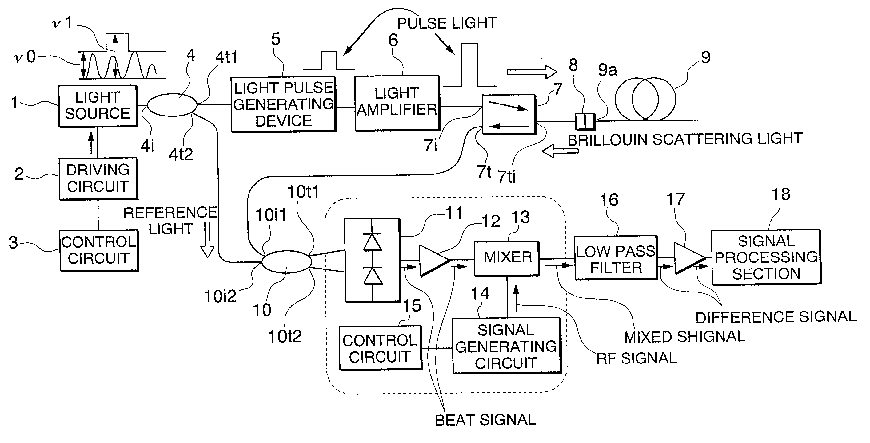
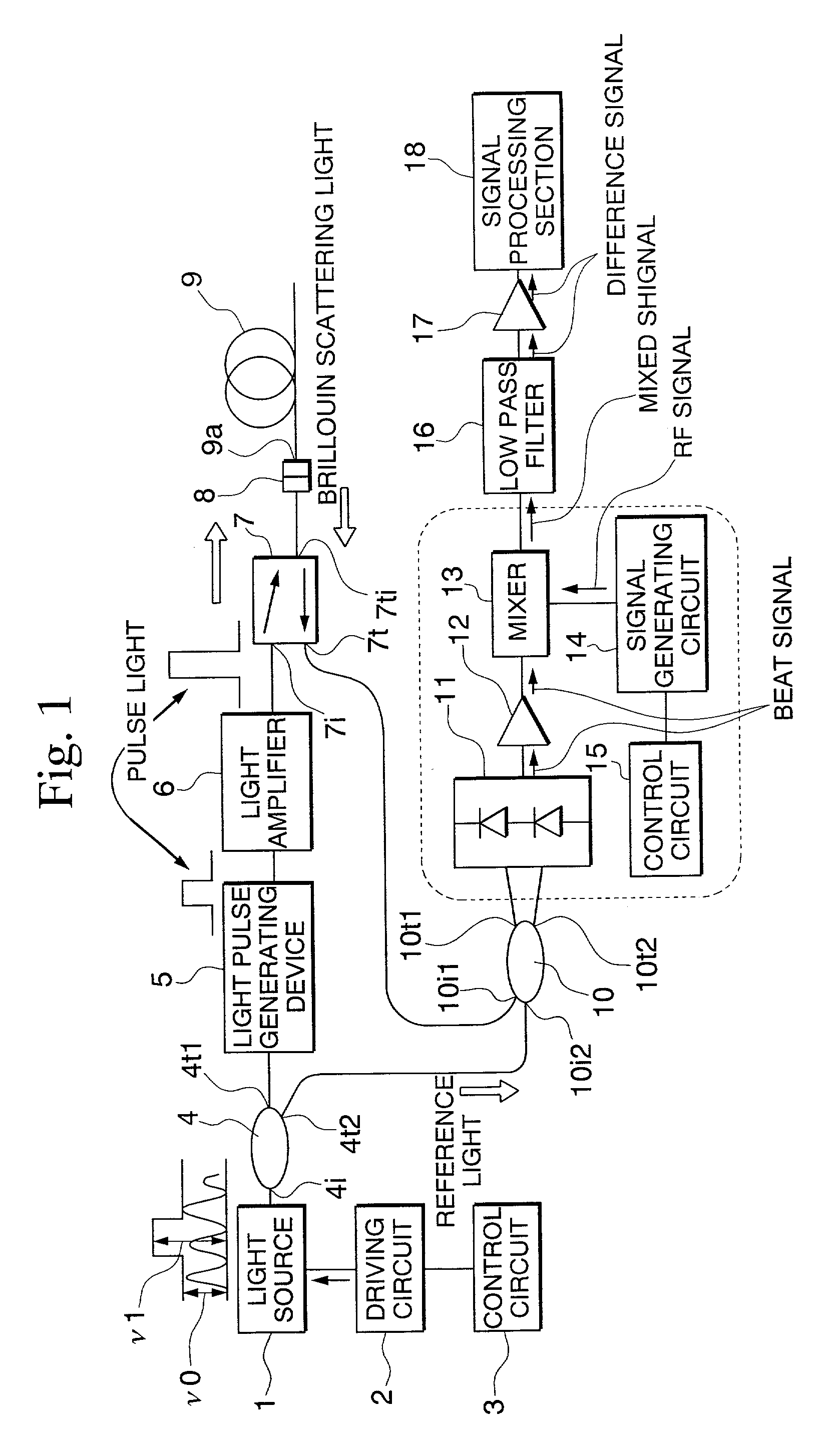
[0030] FIG. 1 is a block diagram showing the structure of an optical fiber characteristic measuring device in an embodiment of the present invention. The light source 1 is specifically a DFB-LD (distributed-feedback laser diode), and emits a coherent light of which the line width is narrow, such as 1.55 .mu.m bandwidth of wavelength .lambda.0, that is, frequency .nu.0 is a bandwidth of 193.55 THz). The wavelength (or the frequency) of the light emitted by the light source 1 slightly changes according to the driving current which is supplied to the light source 1.

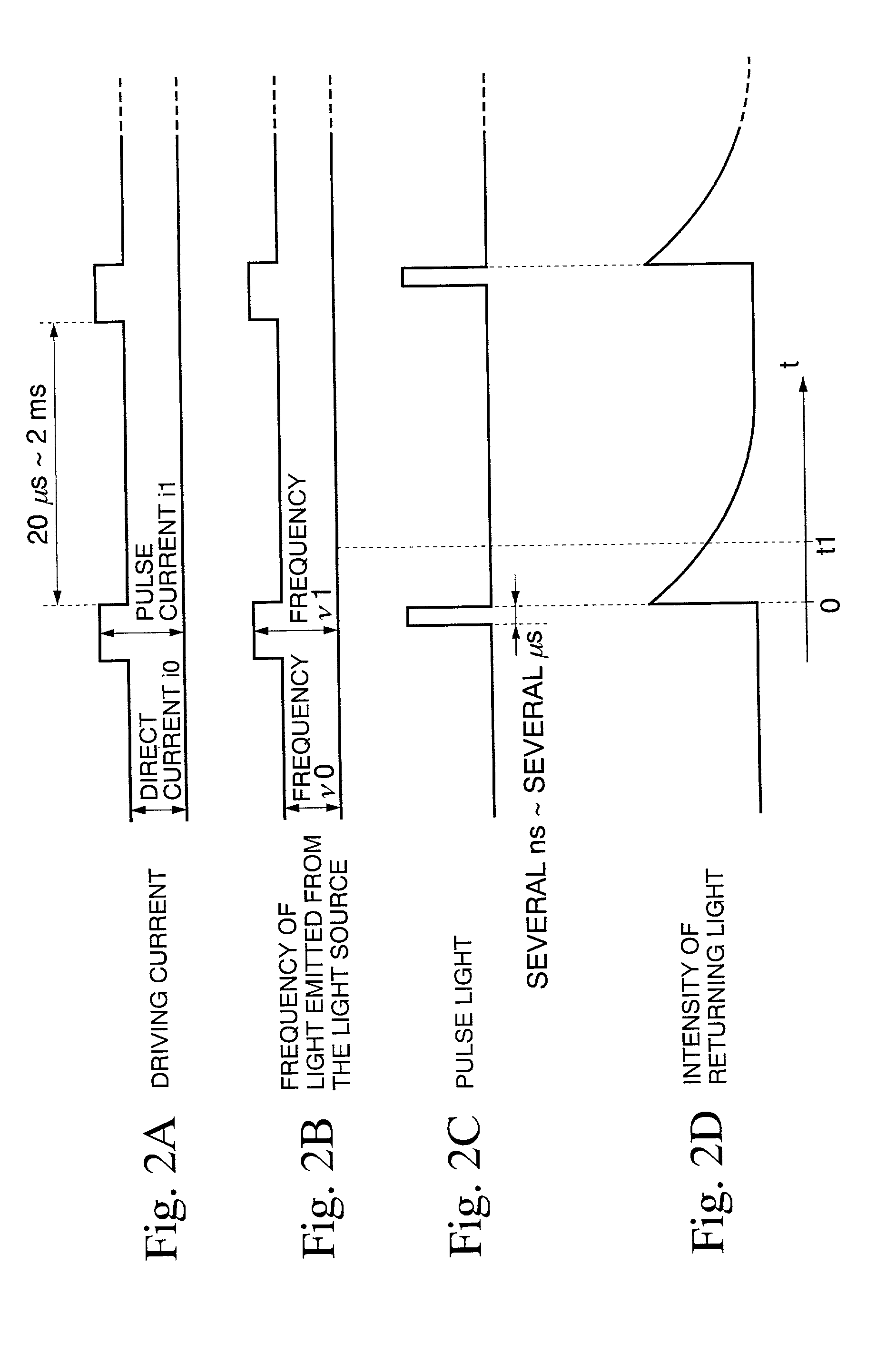
[0031] The driving circuit 2 can supply two kinds of driving current to the light source 1. That is, the driving circuit 2 can supply the driving current i0 to the light source 1, and can also supply the driving current i1 to the light source 1. These driving current values are, for example, i0=70 mA, and i1=80 mA. The control circuit 3 controls the driving circuit 2 and determines the driving current which is supplied to th...


PUM


Abstract

optical fiber characteristic measuring device comprising a coherent light supply device, a light pulse generating device, a wave mixing device, a opto-electrical converting device, and a processing device, is provided such that parts have the frequency characteristic for corresponding to low frequency component for an opto-electrical converting device and a processing section so as to reduce the cost of the circuits.

Description

BACKGROUND OF THE INVENTION[0001] 1. Field of the Invention[0002] The present invention relates to an optical fiber characteristic measuring device which produces a pulse of light incident to an optical fiber as an object to be measured and measures the characteristic of the optical fiber according to the returning light emitted from the optical fiber.[0003] 2. Description of Related Art[0004] FIG. 5 is a block diagram showing a structure of an example of a conventional optical fiber characteristic measuring device. A light of constant frequency of .nu. 0 which is emitted from the light source 1 is incident on an incident port 4i of a first optical directional coupler 4. The first optical directional coupler 4 has an incident port 4i and two emitting ports 4t1 and 4t2. The first optical directional coupler 4 separates the light incident on the incident port 4i into 2 directions and emits the light from the two emitting ports 4t1 and 4t2.[0005] The light which is emitted from the emi...

Claims


Application Information

Patent Timeline
IPC IPC(8): G01M11/02G01M11/00
CPCG01M11/319
Inventor UCHIYAMA, HARUYOSHISAKAIRI, YOSHIYUKI
Owner YOKOGAWA ELECTRIC CORP
Why Eureka
Try Eureka