Electrically driven brake booster

Inactive Publication Date: 2002-10-31
BOSCH AUTOMOTIVE SYST CORP
0 Cites 107 Cited by

AI-Extracted Technical Summary

Problems solved by technology

However, the ball-and-screw mechanism uses an increased number of parts and is complex in arrangement, resulting in disadvantages of an increased weight and a poor transmission efficiency.
In the above disclosures, because the input member and the output member are coupled together integrally, in the event the motor fails for some reason, there results a disadvantage that the master cylinder cannot be directly operated by a driver maneuvering the brake pedal.
However, the electrically driven brake booster of this cited Application suffers from a further complexity in arrangement and an added weight as compared with the boosters disclosed in above Publications.
There also remains another problem in either disclosure that a result of boosting operation by the booster cannot be correctly fe...

Method used

[0035] It is to be noted that in the servo balance condition, a driver may unintentionally reduce the force of depressing the pedal to a degree, but with the electrically driven brake booster 1 according to the present invention which is provided with the reaction disc 25, there is little change in the brake output if the driver reduces the force of depressing the pedal to a degree, whereby a greater reliability can be assured for the driver. This is because there is a difference (hysteresis) between an input upon depression and an input upon release for which a same output is obtained due to the input member 4 (reaction plunger 26) and the reaction disc 25 which is compressed between the output member 5 and the piston 7.
[0039] It will be understood from the foregoing description that with the electrically driven brake booster 1 according to the present invention, part of the brake reaction is transmitted to the brake pedal, thereby permitting a braking operation to be effected accurately. In comparison to an electrically driven brake booster which includes a conventional drive transmitting means, the construction is simple and the weight is reduced. In addition, if the motor 9 fails for some reason, the depression of the brake pedal 12 allows the piston 7 of the master cylinder 6 to be driven forward through the input member 4, the reaction plate 26 and the reaction disc 25 independently from the output member 5, thus achieving a braking action which depends on the force of depressing the brake pedal.
[0041] First, an intensifying function during a quick brake operation will be described. To provide the intensifying function during the quick brake operation, a pair of force of depression-master cylinder liquid pressure characteristic diagrams are stored in the controller 11, one representing a characteristic diagram which prevails during a normal depression and the other another characteristic diagram which prevails during an emergency depression and allowing a greater braking liquid pressure to be obtained. When the force of depressing the brake pedal which is input from the d...

Benefits of technology

0015] According to the first aspect of the invention, the drive transmitting means which comprises the rack and the pinion has a reduced weighed and a simple construction in comparison to a conventional drive transmitting means which comprises a ball and a nut, and has a better transmission efficiency. If the motor fails, the master cylinder can be directl...

Abstract

An electrically driven brake booster 1 includes an input member 4 disposed in operative association with a brake pedal 12, an output member 5 disposed in operative association with the master cylinder 6, and drive transmitting means 10 for translating a rotating motion of a motor 9 into a linear motion to be transmitted to the output member 5. The drive transmitting means 10 comprises a rack 23 formed on the output member 5, and pinions 21, 22 disposed in operative association with the motor 9 and in meshing engagement with the rack 23. Also, reaction transmitting means 8 which transmits a brake reaction to the input member 4 and the output member 5 at a given proportion is provided. In comparison to conventional drive transmitting means, the drive transmitting means 10 of the present invention has a simple construction, a reduced weight and a better transmission efficiency. The provision of reaction transmitting means allows a correct brake control to be achieved on the basis of a brake reaction.

Application Domain

Technology Topic

Image

  • Electrically driven brake booster
  • Electrically driven brake booster
  • Electrically driven brake booster

Examples

  • Experimental program(2)

Example

[0045] FIG. 2 shows a second embodiment of the invention. In the first embodiment, the reaction transmitting means 8 comprises the reaction disc 25 and the reaction plunger 26. However, in the second embodiment, reaction transmitting means 108 comprises a piston 107 of a master cylinder 106 and an input member 104. In other respects, the arrangement is similar to the first embodiment, and accordingly, corresponding parts to those shown in the first embodiment are designated by like reference numerals as used before, to which 100 is added.
[0046] Specifically, a master cylinder 106 includes a substantially tubular piston 107, through which a rod-shaped input member 104 extends slidably, a front end face of the input member 104 directly facing a liquid pressure chamber 106A. The input member 104 comprises a front portion of a reduced diameter 104D which is fitted into an opening of a reduced diameter 107A of the piston 107, and a portion of an increased diameter 104B which continues from the portion 104D and which is fitted into an opening of an increased diameter 107B of the piston 107. A seal ring 130 is provided in the opening of a reduced diameter 107A of the piston 7 to maintain liquid tightness. The piston 107 has a rear end which directly abuts against an output member 105.
[0047] The operation of the electrically driven brake booster 101 will be described. In an inoperative condition shown where a brake pedal 112 is free from depression, the resilience of a return spring 124 urges the brake pedal 112 and the input member 104 rearward, whereby a step 104C on the input member 104 abuts against a stop member 103 and stays at its retracted end position. On the other hand, a controller 111 maintains the output member 105 at its retracted end position where it abuts against the stop member 103.
[0048] If the brake pedal 112 is now depressed, its connected input member 104 is driven forward, and the controller 111 controls a drive current to be applied to a motor 109 on the basis of a depressing force signal from a depressing force sensor 113 and a force of depression-master cylinder liquid pressure characteristic diagram which is previously stored, thus causing the motor 109 to rotate in a forward direction or counter-clockwise as viewed in the drawing at a given rotational speed and with a given torque. Accordingly, a second pinion 122 which meshes with a first pinion 121 rotates clockwise and a rack 123 which meshes with the second pinion 122 is driven forward to urge the piston 107 of the master cylinder 106. A braking liquid is then delivered from the rear liquid pressure chamber 106A of the master cylinder 106 to operate front wheel cylinders 115A for purpose of a braking action. At the same time, a braking liquid pressure is delivered from a front liquid pressure chamber, not shown, to operate rear wheel cylinders 115B for purpose of a braking action.
[0049] When the liquid pressure is generated in the liquid pressure chamber 106A as the piston 107 of the master cylinder 6 is driven forward in response to the operation of the motor 109, the liquid pressure acts upon the front end face of the input member 104, and a resulting force is transmitted, as part of a brake reaction, to the brake pedal 112 through the input member 104, and the liquid pressure in the liquid pressure chamber 106A also acts upon the front end face of the piston 107 to transmit part of the brake reaction to the output member 105.
[0050] Accordingly, the input member 104 ceases to be driven forward at a position where part of the brake reaction transmitted to the brake pedal 112 is balanced with the force of depressing the brake pedal 112, and the output member 105 also ceases to be driven forward at a position where part of the brake reaction transmitted to the output member 105 is balanced with the output from the motor 109, thus achieving a servo balance condition. In the servo balance condition, if brake reactions which are proportioned by the liquid pressure chamber 106A are different from each other, a clearance which is the same as under the inoperative condition is formed between a front step 104E of the input member 104 and the step 107C of the piston 107 since the stroke by which the input member 104 is driven forward and the stroke by which the output member 105 is driven forward are substantially similar.
[0051] When the brake pedal 112 is allowed to return under this condition to reduce the force of depression, its connected input member 104 retracts rearward.
[0052] On the other hand, the controller 111 reverses the rotation of the motor 109 into the clockwise direction and at a given rotational speed while controlling the drive current with a reduction in the force of depressing the brake pedal in accordance with a force of depression-master cylinder liquid pressure characteristic diagram which is previously stored. Accordingly, the second pinion 122 which meshes with the first pinion 121 rotates counter-clockwise, and the rack 123 which meshes with the second pinion 122 causes the output member 105 and the piston 107 to retract rearward.
[0053] When the brake pedal 112 is completely free from depression, the tension of the return spring 124 causes the rear step 104C of the input member 104 to abut against the stop member 103, whereby the input member 104 comes to a stop at its retracted end position shown. On the other hand, the controller 111 causes the motor 109 to rotate clockwise, thus causing the rear end of the output member 105 to abut against the stop member 103, whereby the output member 105 comes to a stop at its retracted end position shown. The reaction disc 125 and the piston 107 are then no longer urged by the input member 104 and the output member 105, and accordingly, the braking liquid pressure becomes zero to cease the braking action.
[0054] If the motor 105 should fail for some reason, the depression of the brake pedal 112 allows the input member 104 to be driven forward independently from the output member 105, allowing the front step 104E of the input member 104 to abut against the step 107C of the piston 107 to urge it, thus permitting the braking action to be obtained by only the force of depressing the brake pedal.
[0055] It will be understood from the foregoing description that the second embodiment allows a similar functioning and effect to be achieved as in the first embodiment except for the jumping response, and the intensifying function during the quick braking operation, the parking retention control function, the regenerative braking coordination function and the automatic brake function can also be applied to this embodiment in the similar manner as applied to the first embodiment.
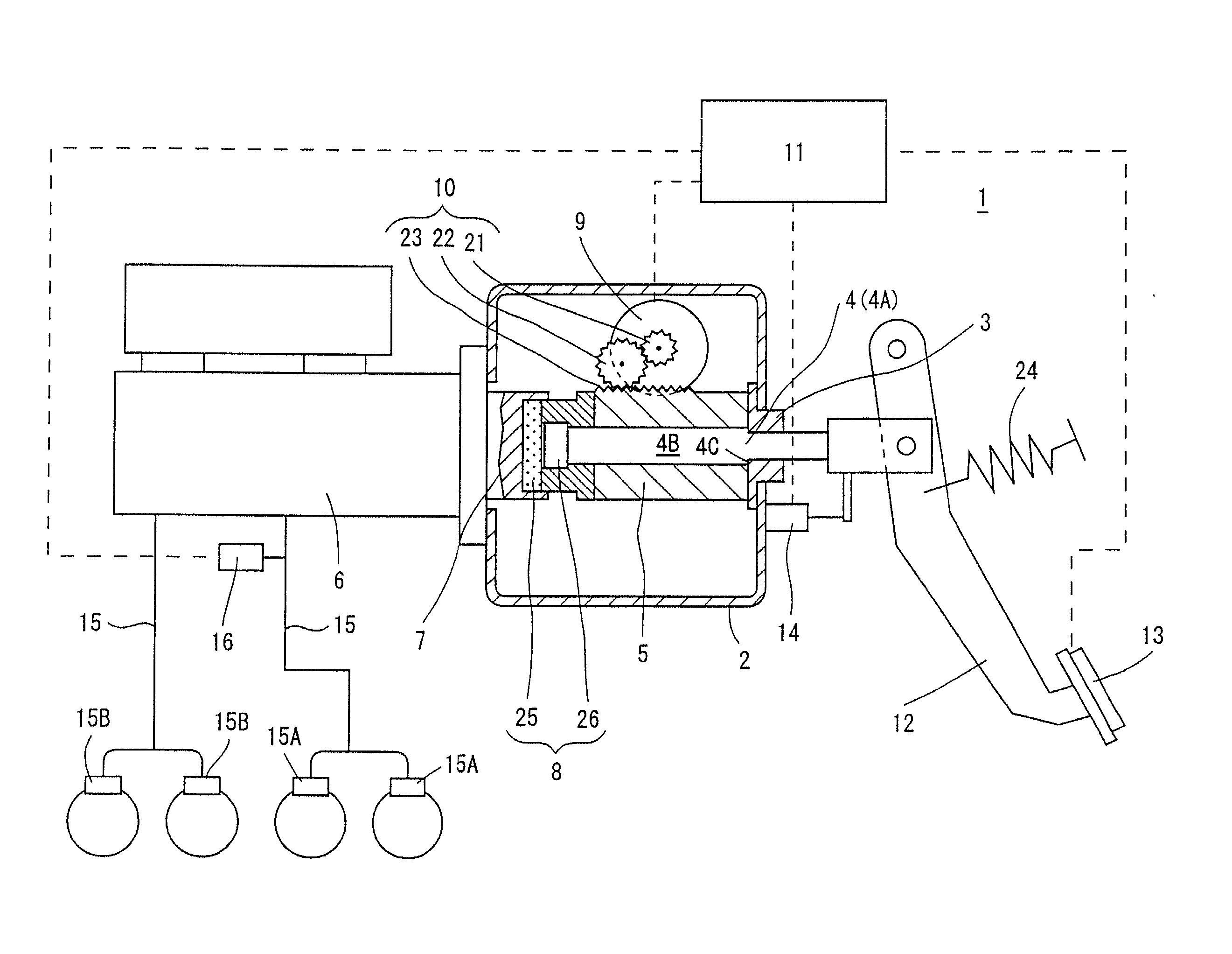
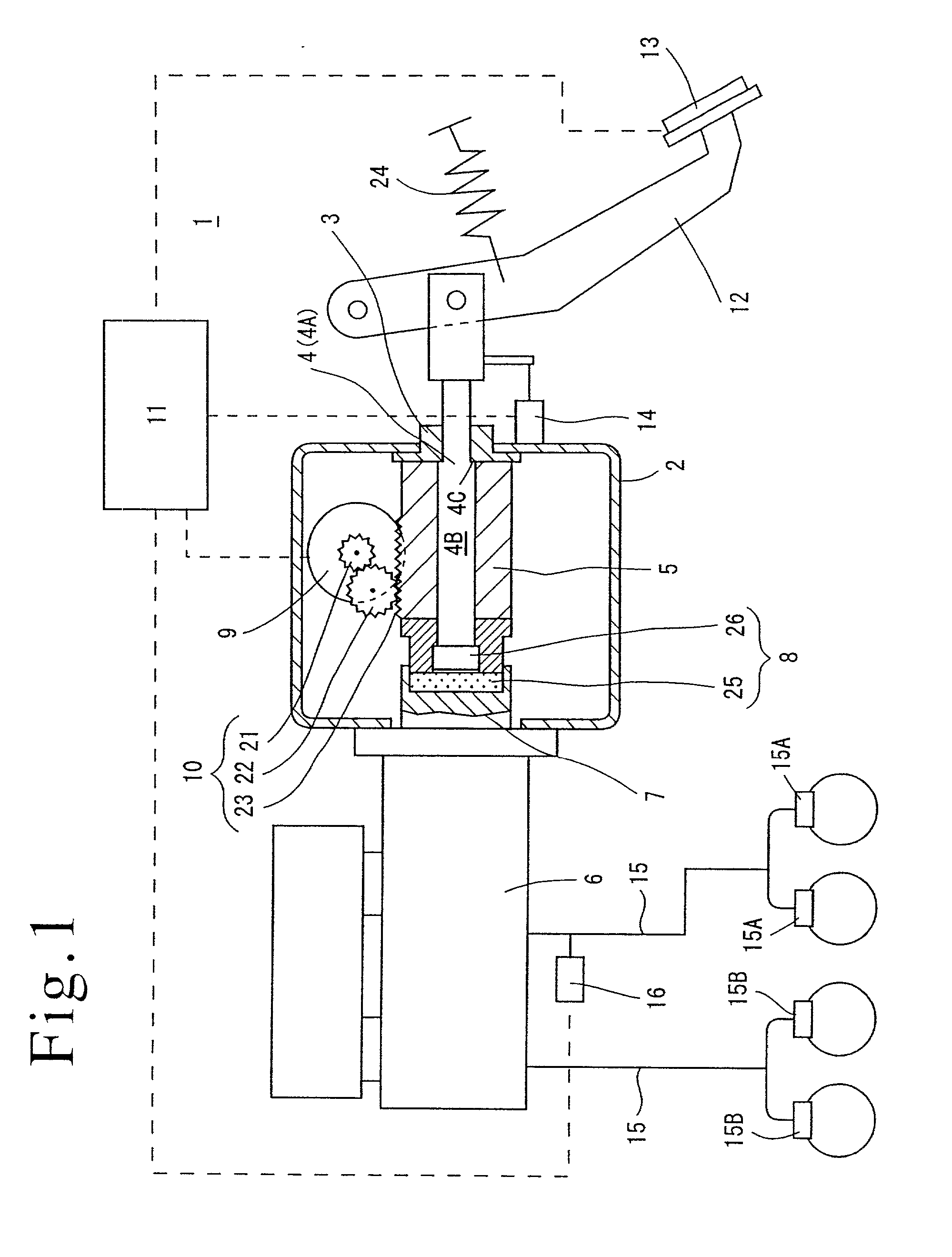
[0056] It is to be noted that in the second embodiment, the input member 104 is arranged to be displaceable relative to the output member 105 and the piston 107 of the master cylinder 106, allowing the strokes of the input member 104 and the output member 105 to be made different from each other. In this manner, the pedal stroke can be set up independently from the stroke of the piston 107 of the master cylinder 106.

Example

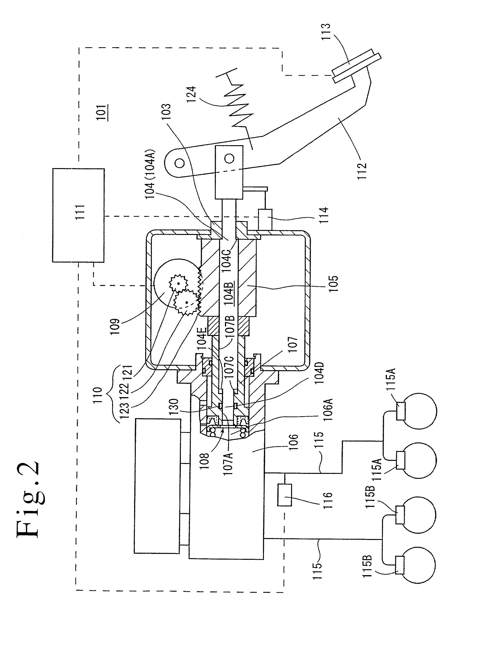
[0057] FIG. 3 shows a third embodiment of the invention. What is modified in the third embodiment over the second embodiment is the provision of a spring 233 disposed between a stop member 203 (a housing 202) and an input member 204 to serve as means for urging the input member 104 in the opposite direction from the direction of the input, allowing the stroke of the input member 204 (or a brake pedal 212) to be set up independently from a stroke of a piston 207.
[0058] In other respects, the third embodiment is arranged in the similar manner as the second embodiment, and accordingly, corresponding parts to those shown in the second embodiment are designated by like reference numerals as used before, to which 100 is added.
[0059] Specifically, as a result of providing the spring 233, an equation for the balance between the input member 204 and the braking liquid pressure is given as follows:
Pm.times.A1+Fs=F1 (1)
[0060] By contrast, an equation for the balance between an output member 205 and the braking liquid pressure is given as follows:
Pm.times.A2=Fm
[0061] where Pm represents a braking liquid pressure in a liquid pressure chamber 206A, A1 a pressure responsive area of the input member 204, Fs the resilience of the spring 233, F1 an input, A2 a pressure responsive area of the output member 204 and Fm a motor thrust.
[0062] The braking liquid pressure Pm is proportional to the input F1 or
Pm=F1 F.times.k1
[0063] The resilience Fs of the spring 233 is given as follows:
Fs=Fs0+k2.times.L
[0064] where Fs0 represents a set load and L a displacement of the spring 233. Accordingly, the equation (1) is rewritten as follows:
F1.times.k1.times.A1+Fs0+k2.times.L=F1
[0065] Rewriting, we have
L=F1.times.(1-k1.times.A1)/k2-Fs0/k2 (2)
[0066] The displacement L of the spring 133 is the same as the stroke of the input member 204, and it is seen from the equation (2) that the stroke of the input member 204 is proportional to the input F1 from the brake pedal 212 and has nothing to do to with the stroke of the output member 205 or the piston of the master cylinder 206. Thus, in the third embodiment, the stroke of the brake pedal can be set up independently from the stroke of the piston of the master cylinder 206.
[0067] It should be obvious that the third embodiment is capable of achieving a similar functioning and effect as achieved by the second embodiment. In addition, because the stroke of the input member 204 is proportional to the input F1, and is not influenced by the stroke of the output member 205 or the piston 207 of the master cylinder 106, the pedal stroke can be freely set up by changing the spring constant of the spring 233 or the pressure responsive area of the input member 204.
[0068] While the invention has been described above in connection with several embodiments thereof, it should be understood that a number of changes, modifications and substitutions therein are possible from the above disclosure without departing from the spirit and the scope of the invention defined by the appended claims.

PUM

no PUM

Description & Claims & Application Information

We can also present the details of the Description, Claims and Application information to help users get a comprehensive understanding of the technical details of the patent, such as background art, summary of invention, brief description of drawings, description of embodiments, and other original content. On the other hand, users can also determine the specific scope of protection of the technology through the list of claims; as well as understand the changes in the life cycle of the technology with the presentation of the patent timeline. Login to view more.

Similar technology patents

Thermal Solution for Prismatic Lithium Ion Battery Pack

ActiveUS20130115506A1Reduce weightCell temperature controlLithium polymer cellThermal solution
Owner:NEOGRAF SOLUTIONS LLC

Distribution method capable of restraining grating lobes of large-space phased-array antenna

InactiveCN103985970ALow costReduce weightIndependent non-interacting antenna combinationsPhysicsGrating lobe
Owner:LINGBAYI ELECTRONICS GRP

Glass film laminate

Owner:NIPPON ELECTRIC GLASS CO LTD

Classification and recommendation of technical efficacy words

  • Reduce weight
  • Simple construction

Nonwoven material for acoustic insulation, and process for manufacture

ActiveUS20100066121A1Improve acoustic propertiesReduce weightCeilingsWallsFibrous layerAirflow
Owner:GLATFELTER CORP

Illumination system for microlithography

ActiveUS20060050261A1Transmission efficiency be highSimple constructionPhotomechanical apparatusPhotographic printingSpatially resolvedLighting system
Owner:CARL ZEISS SMT GMBH
Why Eureka
Try Eureka