Flow control system to reduce memory buffer requirements and to establish priority servicing between networks

a flow control and buffer technology, applied in the field of communication network switching, can solve problems such as signal loss, signal slowing, and inability to address all matters of real or potential importance in networks and internetworks

Inactive Publication Date: 2002-10-31
ENTERASYS NETWORKS
View PDF11 Cites 26 Cited by
  • Summary
  • Abstract
  • Description
  • Claims
  • Application Information

AI Technical Summary

Benefits of technology

[0018] The use of Hardware Flow Control back-pressure to control a group of related ports rather than a single point to point link as it was originally intended allows the multiplexing of several Ethernet ports onto a single port of a dissimilar network type.

Problems solved by technology

However, half duplex connectivity remains a significant portion of existing networks.
While the IETF and the IEEE have been substantially effective in standardizing the operation and configuration of networks, they have not addressed all matters of real or potential importance in networks and internetworks.
When they are, problems include signal loss and signal slowing.
Both are unacceptable conditions as the desire for faster and more comprehensive signal exchange increases.
That approach can be costly and complex and can use up valuable device space.
Matching buffering capacity is generally done in one of two ways, discrete memory components and / or memory arrays implemented in logic cores, e.g., Field Programmable Gate Arrays (FPGAs) or Application Specific Integrated Circuits (ASICs); both methods are costly.
As indicated, adding discrete memory chips increases component count on the board; translating directly into higher cost and lower reliability (higher chance of component failure).
Whereas, implementing memory in logic core devices is gate intensive.
Chewing up logic gates limits functionality within the device that could otherwise be used for enhanced features or improved functionality.

Method used


Image

  • Flow control system to reduce memory buffer requirements and to establish priority servicing between networks
  • Flow control system to reduce memory buffer requirements and to establish priority servicing between networks
  • Flow control system to reduce memory buffer requirements and to establish priority servicing between networks

Examples


Embodiment Construction

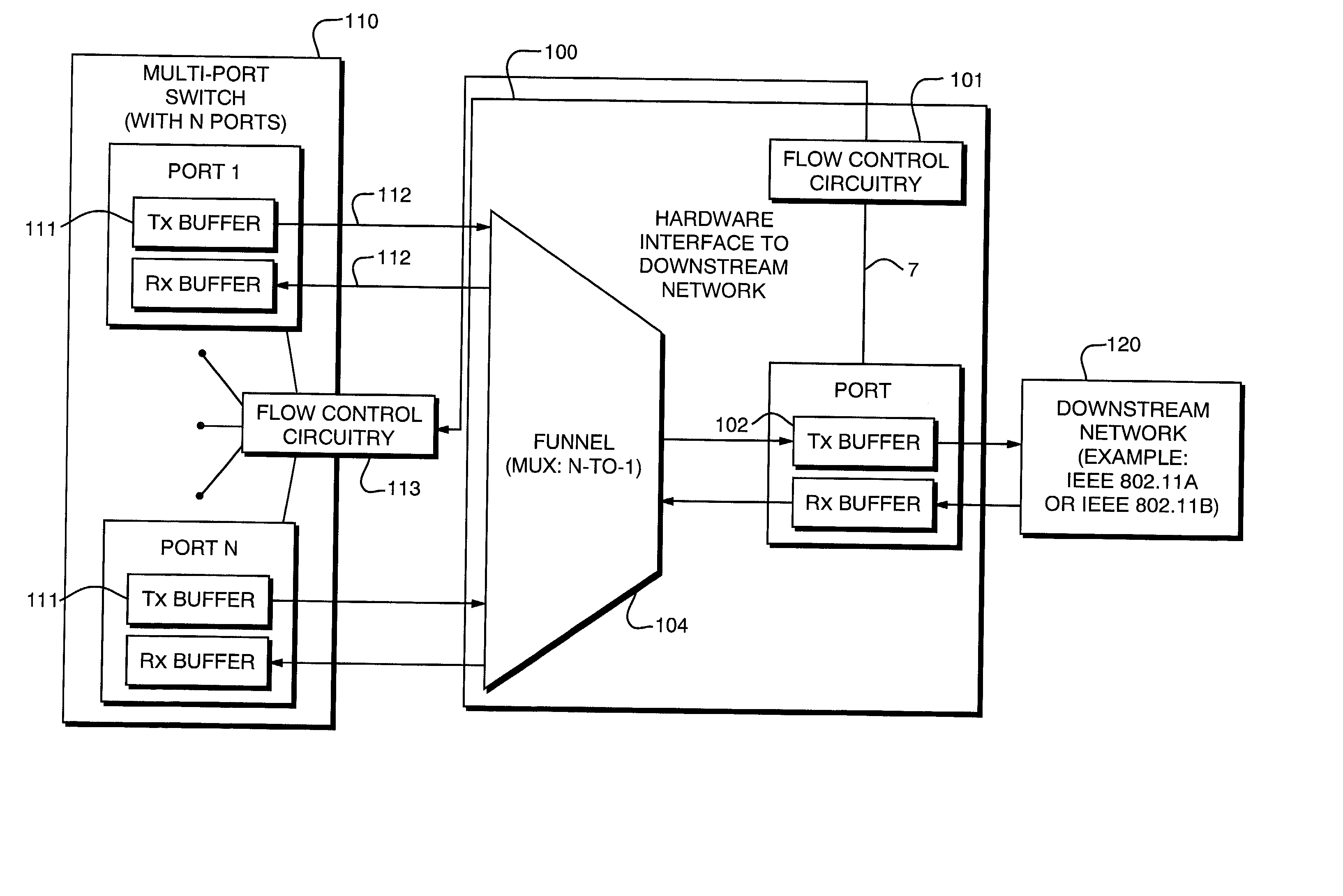
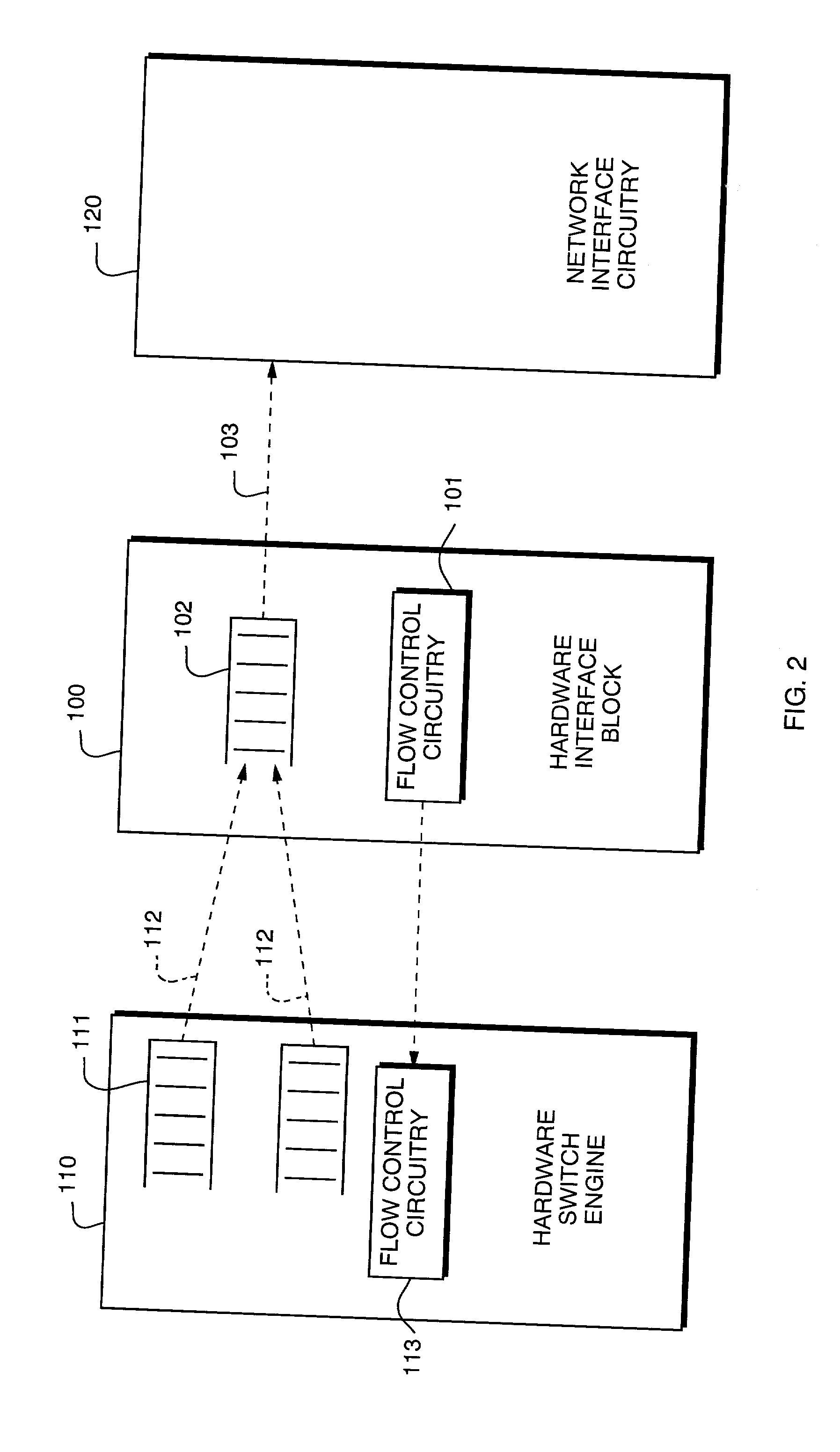
[0027] A flow control system 100 of the present invention is illustrated in simplified form in FIG. 2 in combination with a generic multi-port Ethernet switch engine 110 and network interface circuitry 120 that is not a multi-port device and / or does not transfer data at the same rate that the switch engine 110 does. The switch engine 110 is a common, multi-port Ethernet switch engine used to provide the basic switching functionality including packet storage buffers 111 at output transmit interface 112. An example of a representative device suitable for that purpose is the Matrix.TM. switch offered by Enterasys Networks, Inc. of Portsmouth, N.H. Those skilled in the art will recognize that the switch engine 110 may be any sort of multi-port switching device running any sort of packet switching convention, provided it includes storage buffers or interfaces with suitable storage buffers and transmit interfaces. The flow control system 100 includes flow control circuitry 101 coupled to ...


PUM


Abstract

The invention is a system and method to allow precise control of the transmit packet rate between two different networks and to optionally introduce a priority servicing scheme across several related output ports of a switch engine. The invention employs flow control circuitry to regulate data packet flow across a local interface within a single device by asserting back-pressure. Specifically, flow control is used to prevent a switch port from transmitting a data packet until a subsequent processing stage is ready to accept a packet via that port. The downstream node only permits transmission of packets from the switch when its buffer is available. An interface block effectively multiplexes together multiple switch ports by maintaining constant back-pressure on all of the ports and then releasing the back-pressure, one port at a time, to see if a port has a packet to transmit. This use of back-pressure to control the flow of data packets also allows a priority servicing scheme to be implemented by controlling the sequence of releasing back-pressure to the ports and also the number of packets allowed out of a port when it is allowed to transmit.

Description

[0001] This application claims the priority benefit of provisional U.S. application Ser. No. 60 / 287,502, filed Apr. 30, 2001, of the same title, by the same inventors and assigned to a common owner. The contents of that priority application are incorporated herein by reference.[0002] 1. Field of the Invention[0003] The present invention relates to communications network switching and, in particular, to reduction of memory buffering requirements when interfacing between two networks.[0004] 2. Description of the Prior Art[0005] Computing systems are useful tools for the exchange of information among individuals. The information may include, but is not limited to, data, voice, graphics, and video. The exchange is established through interconnections linking the computing systems together in a way that permits the transfer of electronic signals that represent the information. The interconnections may be either wired or wireless. Wired connections include metal and optical fiber elements...

Claims


Application Information

Patent Timeline
Patent Type & Authority Applications(United States)
IPC IPC(8): G01R31/08G06F15/16H04L12/46H04L12/56H04L25/05
CPCH04L47/10H04L47/14H04L49/552H04L47/263H04L47/30H04L47/2441H04W28/02H04W8/04
Inventor CARRAFIELLO, MICHAEL W.HARAMES, JOHN C.MCGRATH, ROGER W.
Owner ENTERASYS NETWORKS
Why Eureka
Try Eureka