Blade control apparatuses and methods for an earth-moving machine

a control apparatus and earth-moving machine technology, applied in the field of earth-moving machine control apparatus, can solve problems such as severe blade movemen

Inactive Publication Date: 2002-11-07
CARLSON DAVID S +3
View PDF0 Cites 90 Cited by
  • Summary
  • Abstract
  • Description
  • Claims
  • Application Information

AI Technical Summary

Problems solved by technology

In typical prior art systems, when a user moves a portion of the blade across a boundary line the system tends to cause severe blade movement as it attempts to compensate for the discontinuous design surface.

Method used


Image

  • Blade control apparatuses and methods for an earth-moving machine
  • Blade control apparatuses and methods for an earth-moving machine
  • Blade control apparatuses and methods for an earth-moving machine

Examples


Embodiment Construction

.

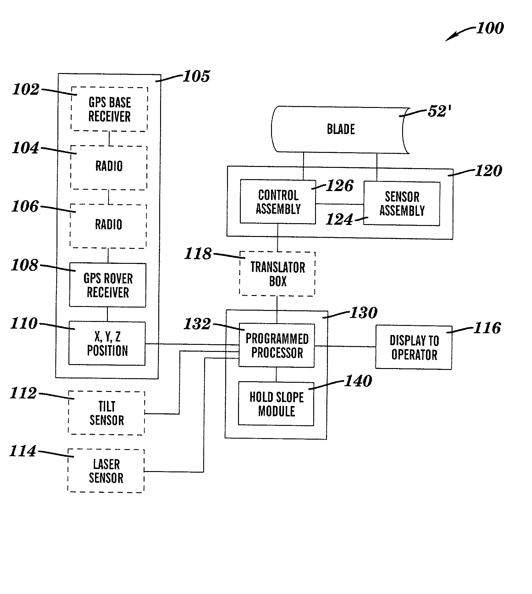
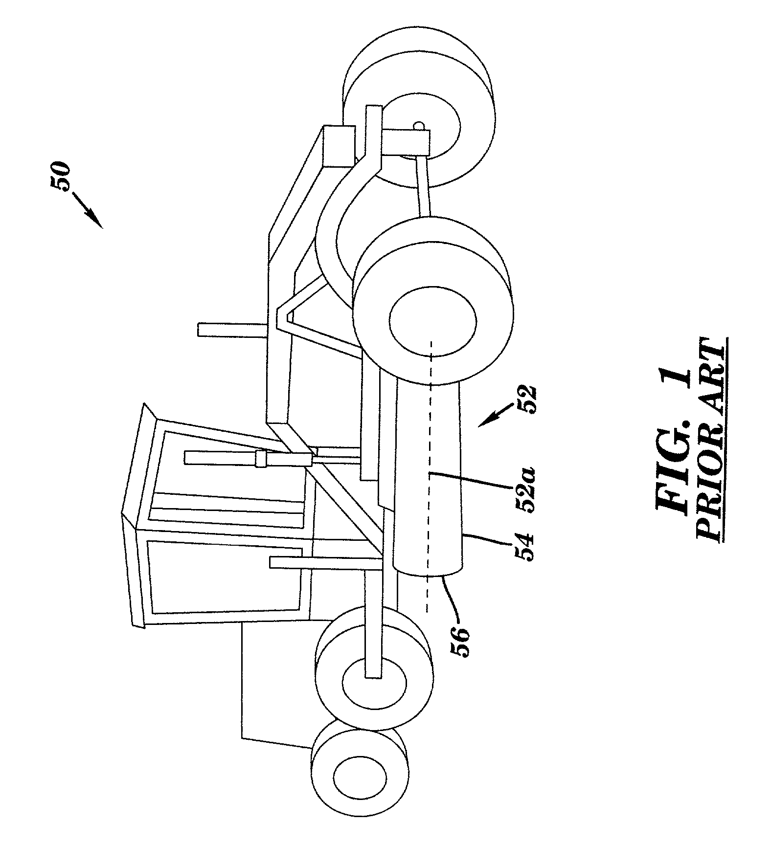
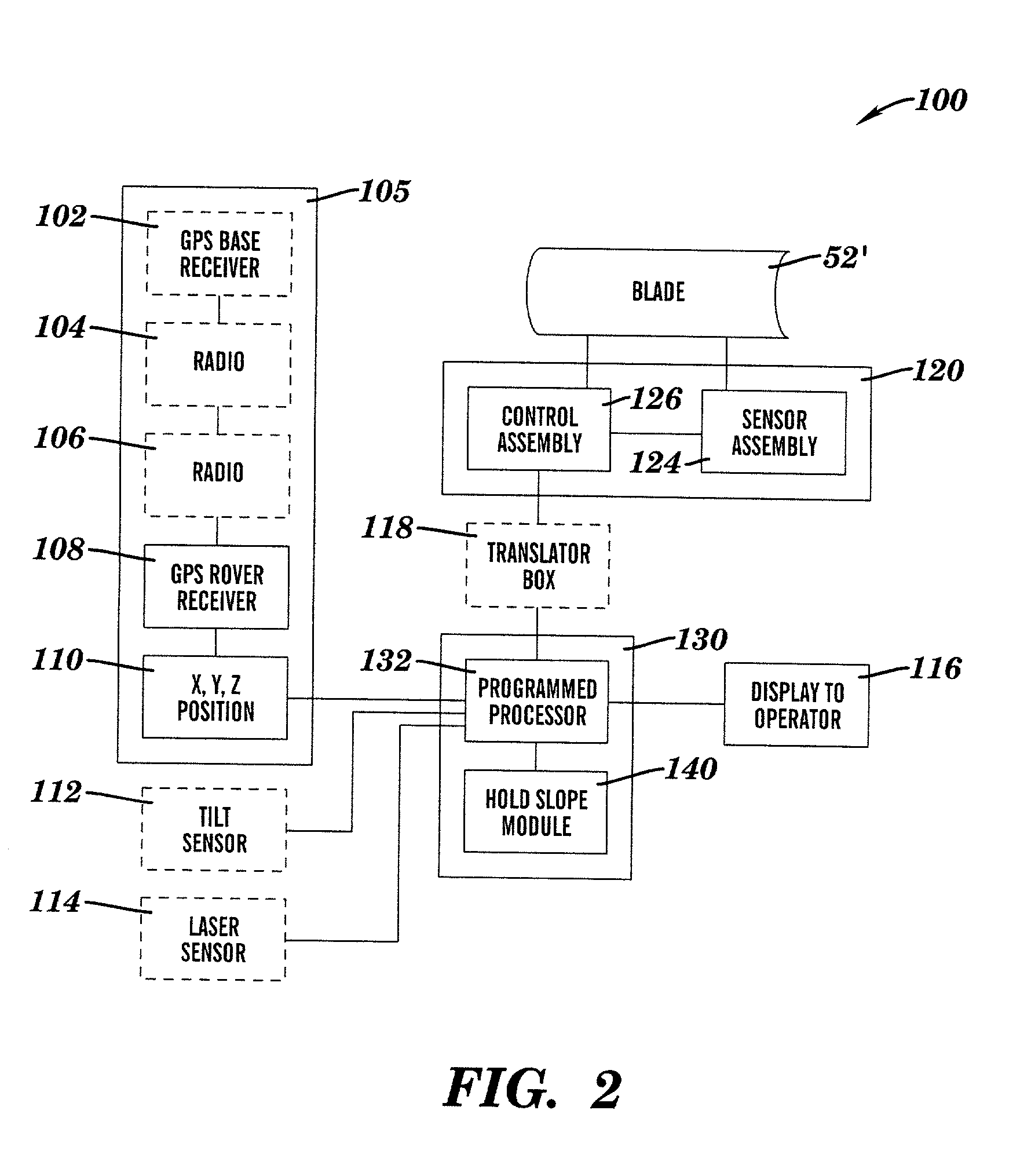
[0031] Where used in this disclosure, the terms "computer" and / or "programmed processor" shall refer to any suitable processing device including, a programmable digital computer, microprocessor, microcontroller, etc., including dedicated, embedded, and general purpose computers and workstations. As used herein, the terms "earth-working machine", "earth-working vehicle", and "geography altering machine" shall refer to any self-propelled, mobile machine, such as graders, bulldozers, tractors, loaders, and the like that have the capacity to alter the geography of a worksite. The term "blade" shall refer to the implement or tool by which an earth-working machine alters the geography of a worksite, such as a blade, a mold board, a plow, a bucket or a shovel. Blade 52, 52' (FIGS. 1-4) includes a longitudinal cutting edge 54 that extends substantially parallel to longitudinal axis 52a. Blade 52, 52' may further include one or more transverse cutting edges disposed at opposite ends 56 ther...


PUM


Abstract

A method and apparatus for providing for real time automated control of the position of a blade on a earth-moving machine. The method includes providing a geography altering machine, including a blade and a computer, the computer having stored therein a reference line and a three dimensional computer model of a desired topography, providing a user defined offset relative to the reference line, determining a blade position in local coordinates, converting the local coordinates to reference line coordinates, utilizing the reference line coordinates and the user defined offset to calculate blade movement commands, and moving the blade in a direction required by the blade movement commands.

Description

[0001] (1) Field of the Invention[0002] The present invention generally relates to earth-working systems, and more particularly, to an apparatus and method for providing real time control of a cutting blade.[0003] (2) Background Information[0004] Relatively sophisticated and powerful geography altering, earth-moving, and / or earth-working machinery have been developed to recontour the topography of large tracts of land, or to otherwise alter the geography of a worksite such as a construction area, a mine, a roadbed, an airport runway, and the like. Machinery of this type (e.g., motor graders and bulldozers) typically include a cutting blade for cutting or sculpting the desired contour as shown in FIG. 1, which is a schematic of a motor grader 50 including a cutting blade 52 (also referred to as a mold board) for contouring a tract of earth.[0005] The advent of computer technology and navigational systems such as satellite, laser, and gyroscope methods has led to the development of va...

Claims


Application Information

Patent Timeline
Patent Type & Authority Applications(United States)
IPC IPC(8): E02F3/84E02F9/26G01S19/04G01S19/10G01S19/44G01S19/46
CPCE02F3/847Y10S37/907Y10S37/906E02F9/26
Inventor CARLSON, DAVID S.BROOKS, JAMES R.SOCZAWA, RONALD H.ROGERS, FREDERICK A.
Owner CARLSON DAVID S
Why Eureka
Try Eureka