Bone graft and implantable fusion stimulator positioning device

a positioning device and bone graft technology, applied in the field of bone fusions, can solve the problems of inexact placement of bone graft in spinal fusion and in proximity to fractures, failure of spinal fusion healing, and soft tissue interposition

Inactive Publication Date: 2002-11-07
WILSON CHRIS EDWARD
View PDF0 Cites 42 Cited by
  • Summary
  • Abstract
  • Description
  • Claims
  • Application Information

AI Technical Summary

Problems solved by technology

The placement of bone graft in spinal fusions and in proximity to fractures is inexact despite careful surgical technique.
There is a potential for migration of the graft, unequal distribution of material, and the risk of soft tissue interposition among graft pieces or between the bone and bone graft interface The result of these occurrences is an ineffective surgical procedure and, often, failure of healing of a spinal fusion or of a long bone fracture that has been grafted
Pitfalls arise first from uneven dispersal of the graft material as the surgeon's view is often obstructed by soft tissue or by bone graft already implanted.
Placement of larger quantities of graft often results in migration of material by simple mass effect.
Finally, margins of the soft tissue about the pocket are often friable and loose.
Soft tissue containment of the graft is frequently inadequate.

Method used


Image

  • Bone graft and implantable fusion stimulator positioning device
  • Bone graft and implantable fusion stimulator positioning device
  • Bone graft and implantable fusion stimulator positioning device

Examples


Embodiment Construction

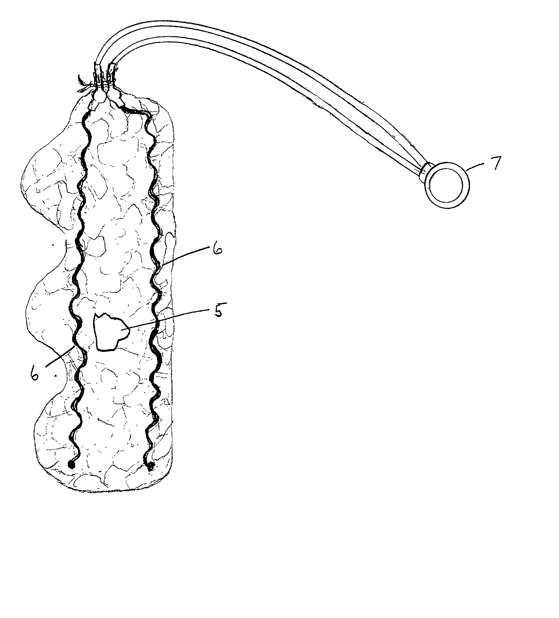
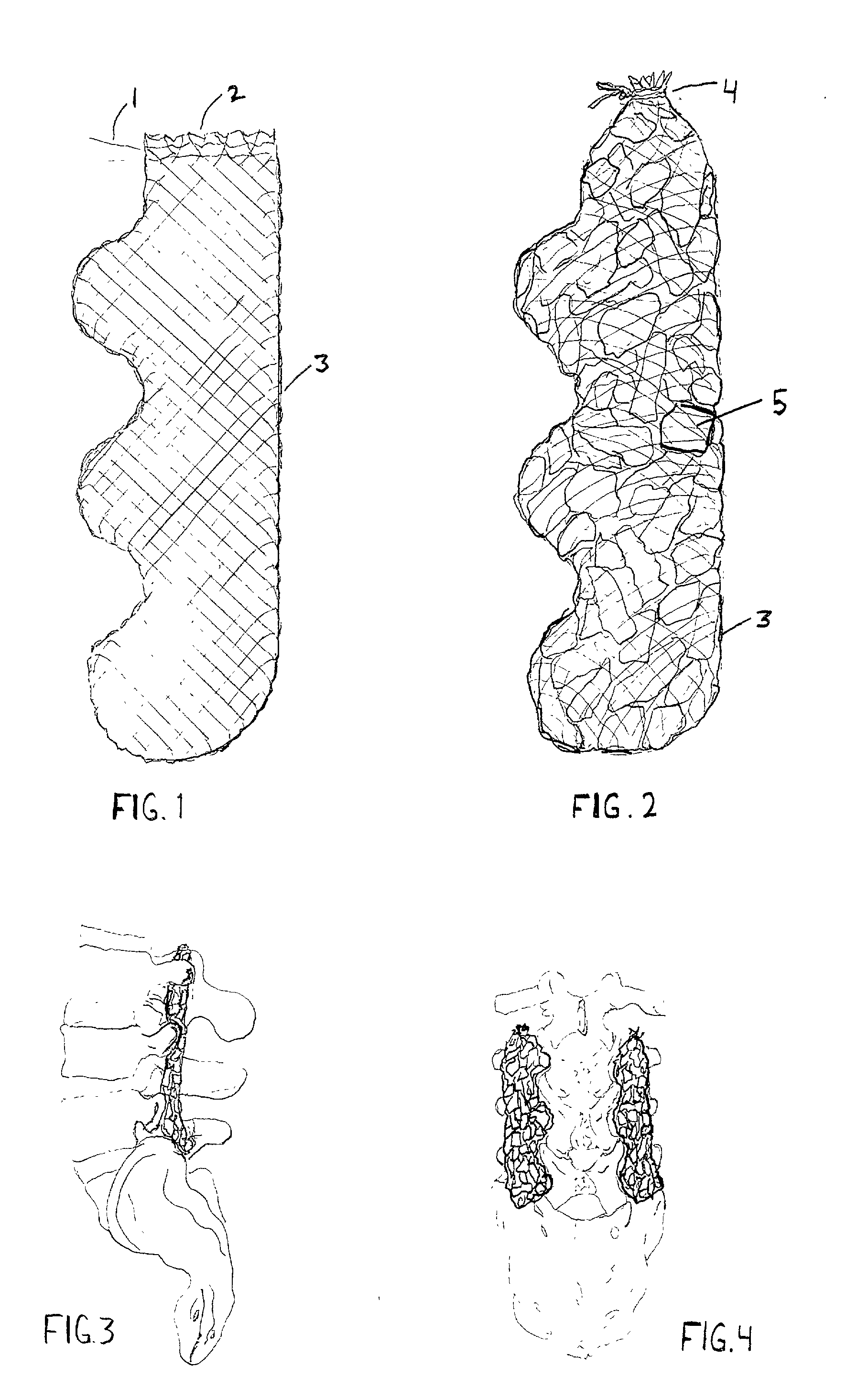
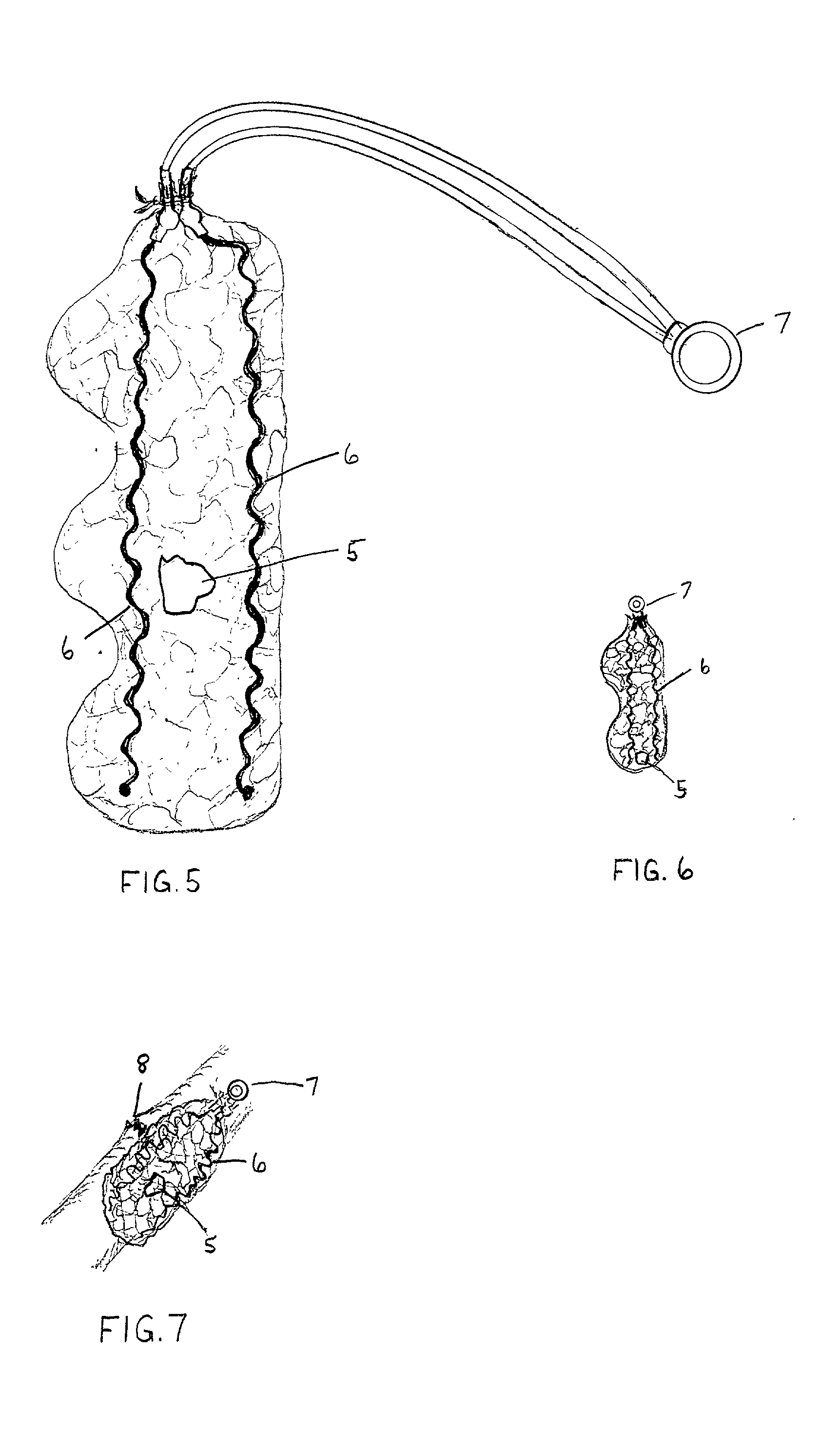
[0028] A preferred embodiment of the closure of the present invention is illustrated in FIGS. 3, 4, and 7. The bio-absorbable mesh sac has been filled with bone graft material 5 and the device sealed 4 by drawstrings 1 positioned at one end of the device. The invention is then placed in the proximity of desired fusion or fracture healing (FIGS. 3, 4, and 7). In FIG. 7 an implantable source of current 7 with cathode leads 6 have been bonded to the sac in a coordinated arrangement.

[0029] FIG. 1 depicts a basic containment device contoured to fit intimately about the posterior lumbar spine. Small caliber absorbable suture, such a Monocryl by Johnson & Johnson, is woven in a "fishnet" manner and bonded about its outer edge 3. The top portion of the sac 2 is left open in the drawing but contains draw-stings 1 that will be closed and tied at the time of surgery 4. Placement of graft material within the sac is aided by a supplied, folded, portion of paper that is removed from the opening a...


PUM


Abstract

A sac composed of woven bio-absorbable suture with an opening (2) for placement of bone graft or bone graft substitutes (5). The device is contoured and sized for positioning in various anatomic areas (FIGS. 3, 4, and 7) and may be coupled to an implantable electronic fusion stimulator device (6 and 7).

Description

[0001] Not applicable.[0002] 1. Field of Invention[0003] This device relates to bony fusions in the spine and in the long bones. Specifically, the device allows for appropriate dispersal and containment of bone graft and bone graft substitutes as well as for proper positioning of wire leads used in implantable electrical stimulators of bone and fusion healing.[0004] 2. Description of Prior Art[0005] The placement of bone graft in spinal fusions and in proximity to fractures is inexact despite careful surgical technique. There is a potential for migration of the graft, unequal distribution of material, and the risk of soft tissue interposition among graft pieces or between the bone and bone graft interface The result of these occurrences is an ineffective surgical procedure and, often, failure of healing of a spinal fusion or of a long bone fracture that has been grafted[0006] Attempts at increasing the rates of success of spinal fusion and grafting of long bone fractures have focuse...

Claims


Application Information

Patent Timeline
Patent Type & Authority Applications(United States)
IPC IPC(8): A61N1/05
CPCA61N1/05
Inventor WILSON, CHRIS EDWARD
Owner WILSON CHRIS EDWARD
Why Eureka
Try Eureka