Common rail system

a common rail system and rail technology, applied in the direction of fuel injection with sensors, machines/engines, mechanical equipment, etc., can solve the problem that the space occupation of injectors with control valves is relatively larg

Inactive Publication Date: 2002-11-21
ROBERT BOSCH GMBH
View PDF10 Cites 1 Cited by
  • Summary
  • Abstract
  • Description
  • Claims
  • Application Information

AI Technical Summary

Problems solved by technology

The injectors with a control valve occupy a relatively large

Method used


Image

  • Common rail system
  • Common rail system
  • Common rail system

Examples


Embodiment Construction

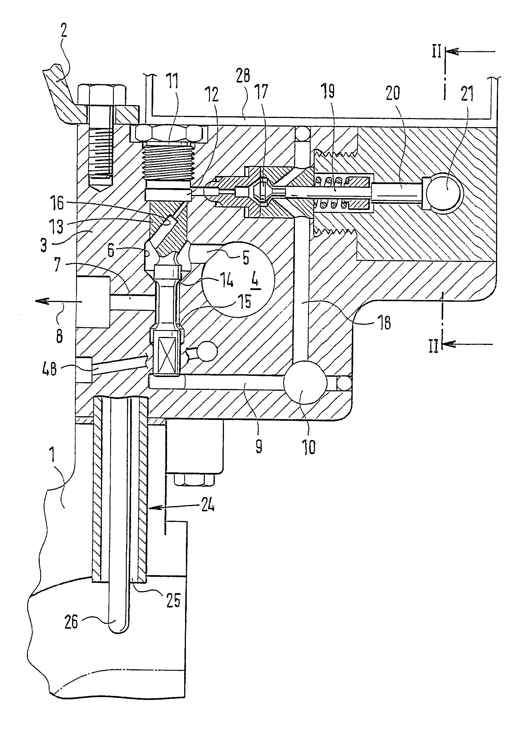
[0015] In FIG. 1, a detail of a cylinder head 1 of a motor vehicle engine is seen. The top of the cylinder head 1 is covered by a cylinder head cap 2. Disposed between the cylinder head cap 2 and the cylinder head 1 is a module 3 of a common rail fuel injection system.

[0016] A central high-pressure fuel reservoir 4 is embodied in the module 3. The high-pressure fuel reservoir 4 takes the form of a bore, which extends into the plane of the drawing. A high-pressure fuel conduit 5 extends from the high-pressure fuel reservoir 4. The high-pressure fuel conduit 5 discharges into a bore 6, whose longitudinal axis is disposed perpendicular to the longitudinal axis of the high-pressure fuel reservoir 4.

[0017] A high-pressure conduit 7 is extends from the valve bore 6. Through the high-pressure conduit 7, fuel subjected to high pressure flows out of the high-pressure fuel reservoir 4 to an injection nozzle, represented by an arrow 8. A return from the injection nozzle (not shown) is marked 4...


PUM


Abstract

The invention relates to a common rail system for supplying fuel to internal combustion engines, in particular Diesel engines of passenger cars, having a central high-pressure fuel reservoir (4), which via high-pressure fuel lines (5, 7) communicates with a plurality of injectors, whose opening and closing motions are controlled each by a respective control device (13; 17, 19). In order to furnish a common rail system that is suitable for vehicle engines, the high-pressure fuel reservoir (4) and the control devices (13; 17, 19) are combined in a module, which communicates permanently with the injectors via high-pressure fuel lines (8, 48).

Description

PRIOR ART[0001] The invention relates to a common rail system for supplying fuel to internal combustion engines, in particular Diesel engines of passenger cars, having a central high-pressure fuel reservoir, which via high-pressure fuel lines communicates with a plurality of injectors, whose opening and closing motions are controlled each by a respective control device.[0002] In common rail injection system, a high-pressure pump, optionally with the aid of a prefeed pump, pumps the fuel to be injected from a fuel tank into the central high-pressure fuel reservoir, which is known as a common rail. From the rail, fuel lines lead to the individual injectors, which are assigned to the cylinders of the engine. The injectors are triggered individually as a function of the engine operating parameters with the aid of a control unit, so as to inject fuel into the combustion chamber of the engine.[0003] From German Patent Disclosure DE 197 01 879, a fuel injection system for large Diesel engi...

Claims


Application Information

Patent Timeline
IPC IPC(8): F02M39/00F02M47/00F02M51/06F02M55/02F02M63/00
CPCF02F2007/0097F02M39/00F02M55/025F02M2200/24F02M63/0007F02M2200/21F02M63/0005
Inventor POLACH, WILHELMBOECKING, FRIEDRICH
Owner ROBERT BOSCH GMBH
Why Eureka
Try Eureka