MPEG encoder control protocol for on-line encoding and MPEG data storage

a control protocol and encoder technology, applied in the field of compressed visual data processing, can solve the problems of buffer overflow, uncompressed audio and video splicing, and uncompressed audio/visual splicing,

Active Publication Date: 2002-11-21
EMC IP HLDG CO LLC
View PDF16 Cites 69 Cited by
  • Summary
  • Abstract
  • Description
  • Claims
  • Application Information

AI Technical Summary

Problems solved by technology

The splicing of MPEG encoded audio / visual streams, however, is considerably more difficult than splicing of the uncompressed audio and video.
Moreover, because a video decoder buffer is required to compensate for the uneven spacing of the frame boundaries in the encoded streams, splicing may cause underflow or overflow of the video decoder buffer.
In either case, however, it is possible that the spliced stream will cause buffer overflow.
The Society of Motion Picture and Television Engineers (SMPTE) apparently thought that the ISO MPEG-2 standard was inadequate with respect to splicing.
If frame accuracy is not ensured, then desired frames will be missing from the spliced video stream, and undesired frames will appear in the spliced video stream.
If frame inaccuracy accumulates, there could be serious schedule problems.
The loss or addition of one or more frames is especially troublesome when commercials are inserted into program streams.
More importantly, the loss or addition of just a few frames may result in a substantial loss of income from advertisers, because advertisers are charged a high price for each second of on-air commercial time.
However, if a clip is to be used in a splicing operation and the In-point for the clip is not an I-frame in the clip or the Out-point is not the last frame of a GOP, then the splicing operation may require additional processing or result in undesirable visual artifacts or have the effect of introducing frame inaccuracy.
The encoded MPEG-2 clip could be decoded and re-encoded off-line so that the desired In-point and Out-point are valid and desirable splice points for seamless splicing, but such decoding and re-encoding requires significant processing time and resources.

Method used


Image

  • MPEG encoder control protocol for on-line encoding and MPEG data storage
  • MPEG encoder control protocol for on-line encoding and MPEG data storage
  • MPEG encoder control protocol for on-line encoding and MPEG data storage

Examples


Embodiment Construction

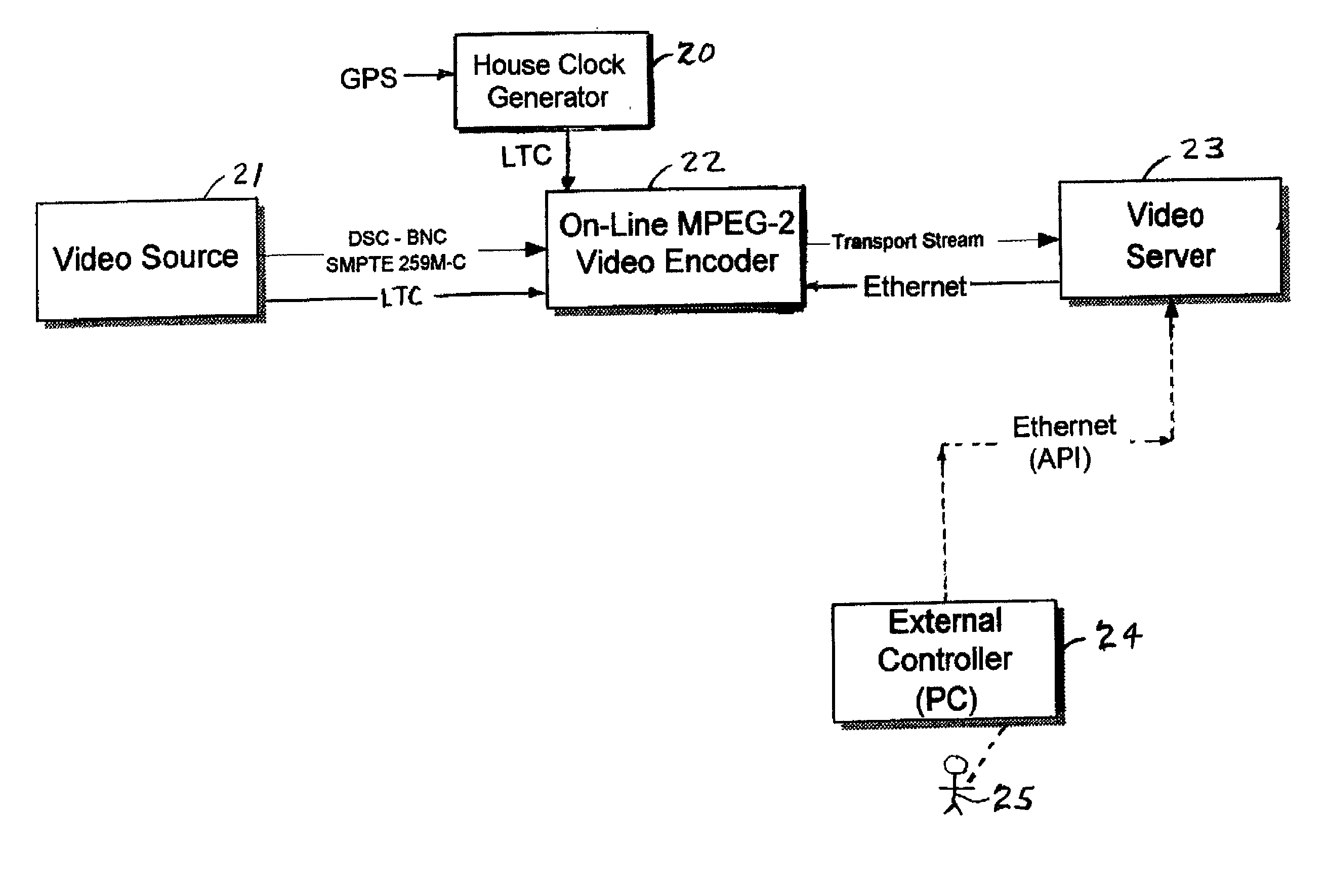
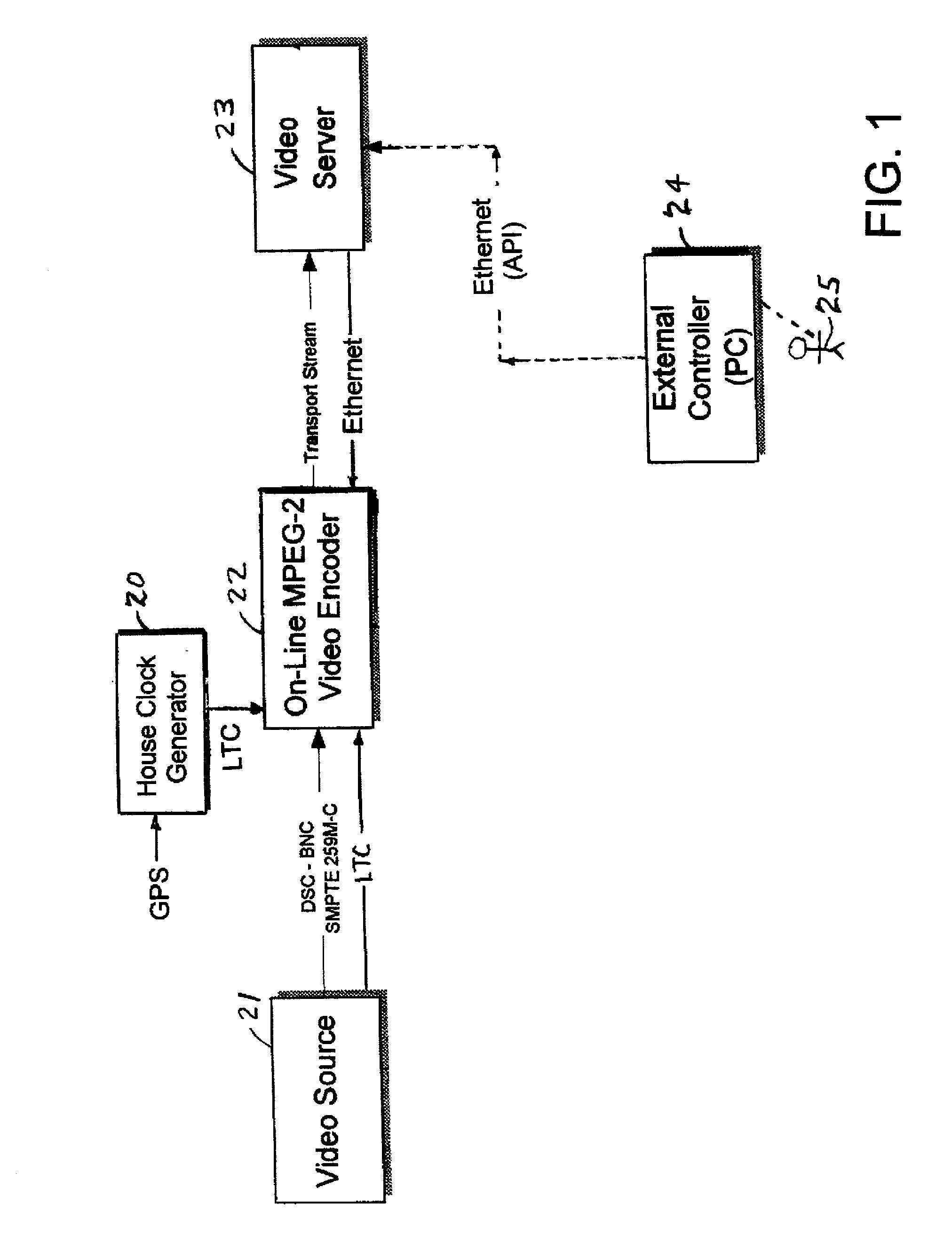
[0072] With reference to FIG. 1, there is shown a digital video recording system including a video source 21, an on-line MPEG-2 video encoder 22, a video server 23, an external controller 24, and a house clock generator 20 synchronized to a global positioning system (GPS) clock signal. As used herein, the term "on-line" is intended to be synonymous with "real-time." The video source 21, such as a TV camera, video tape deck, or video disk player, provides a digital video signal over a digital serial channel (DSC) using a coaxial cable connection (BNC). For example, the video source may include an NTSC or PAL composite video signal, or a digital serial channel compliant with the serial digital interface (SDI) standard, and in particular the International Telecommunications Union standard ITU-R-656 or the SMPTE standard RS259. The on-line MPEG-2 video encoder 22 provides an MPEG-2 Transport Stream (TS) to the video server 23. The video server 23 is a storage system for storing video cl...


PUM


Abstract

Coded video from an on-line MPEG video encoder is stored as a clip in a video server or is otherwise received in the video server and prepared or used for splicing. In order to reduce apparent frame inaccuracy that may result from the splicing process, the on-line MPEG video encoder and the server are coordinated so that the group-of-picture (GOP) structure in the encoder provides specified In-points and Out-points that are valid and desirable for splicing. An encoder control protocol is also provided for remote control of the on-line MPEG video encoder in order to coordinate the on-line MPEG video encoder with the video server.

Description

[0001] 1. Field of the Invention[0002] The present invention relates to processing and storage of compressed visual data, and in particular the on-line encoding of MPEG data for storage, splicing, or other processing in a video server.[0003] 2. Background Art[0004] It has become common practice to compress audio / visual data in order to reduce the capacity and bandwidth requirements for storage and transmission. One of the most popular audio / video compression techniques is MPEG. MPEG is an acronym for the Moving Picture Experts Group, which was set up by the International Standards Organization (ISO) to work on compression. MPEG provides a number of different variations (MPEG-1, MPEG-2, etc.) to suit different bandwidth and quality constraints. MPEG-2, for example, is especially suited to the storage and transmission of broadcast quality television programs.[0005] For the video data, MPEG provides a high degree of compression (up to 200:1) by encoding 8.times.8 blocks of pixels into ...

Claims


Application Information

Patent Timeline
Patent Type & Authority Applications(United States)
IPC IPC(8): G06T9/00H04N7/26H04N21/234H04N21/44H04N21/845
CPCH04N21/23412H04N21/23424H04N19/87H04N21/8455H04N19/46H04N21/44016
Inventor MANTCHALA, RAYMONDFORECAST, JOHNBIXBY, PETERFAIBISH, SORINNOURY, MICHELDUSO, WAYNE W.
Owner EMC IP HLDG CO LLC
Why Eureka
Try Eureka