
Digital signal processing of resolver rotor angle signals

a technology of resolver and rotor, which is applied in the field of digital signal processing of resolver rotor angle signals, can solve the problems affecting the effectiveness and reliability of conventional tracking converters, and being subject to various noises

Inactive Publication Date: 2002-11-21
RAYTHEON CO
View PDF0 Cites 46 Cited by
  • Summary
  • Abstract
  • Description
  • Claims
  • Application Information

AI Technical Summary

Problems solved by technology

In a real world environment, the tracking converter will be subjected to noise of various kinds.
This requires a design with good noise immunity because if noise exceeds the system immunity of the tracking converter, the rotor angle, or gimbal position, fed to other systems will not be accurate leading to improper navigation and guidance of the missile.
The conventional tracking converter, while effective and reliable at tracking a resolver rotor angle, such as a gimbal shaft angle in a guided missile, is problematic because of cost.
However, since digital signaling processing is inherently a sampling process, it is sensitive to noise.

Method used


Image

  • Digital signal processing of resolver rotor angle signals
  • Digital signal processing of resolver rotor angle signals
  • Digital signal processing of resolver rotor angle signals

Examples


Embodiment Construction

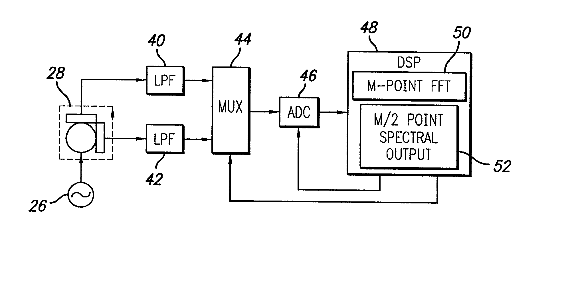
[0023] Illustrative embodiments and exemplary applications will now be described with reference to the accompanying drawings to disclose the advantageous teachings of the present invention. While the present invention is described herein with reference to illustrative embodiments for particular applications, it should be understood that the invention is not limited thereto. Those having ordinary skill in the art and access to the teachings provided herein will recognize additional modifications, applications, and embodiments within the scope thereof and additional fields in which the present invention would be of significant utility.

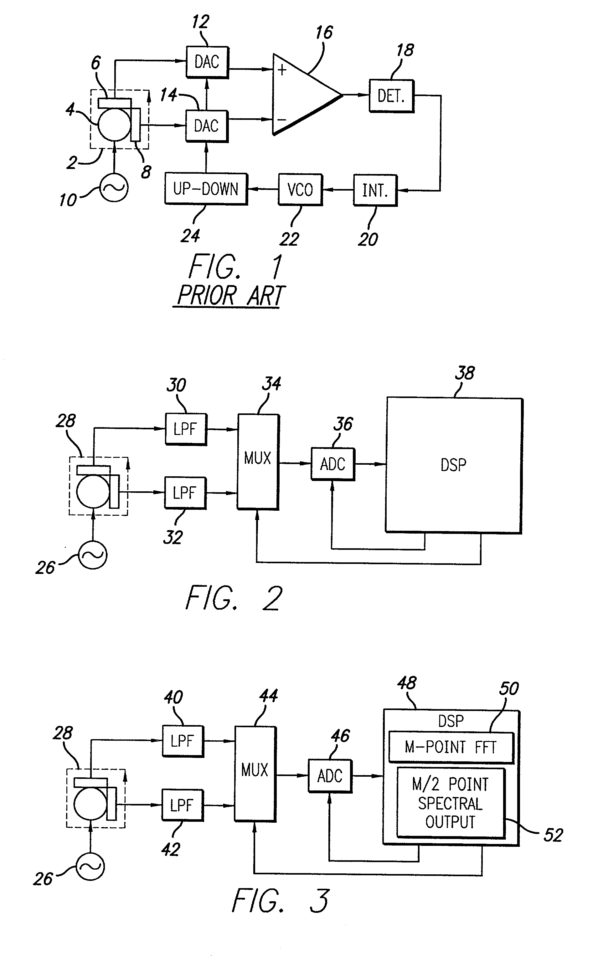
[0024] Reference is directed to FIG. 1 which depicts the prior art resolver and tracking converter circuit. The resolver 2 includes a rotor 4 which has an electric coil winding that is excited by an oscillator 10 that supplies a sinusoidal oscillating reference voltage generally described by:

[0025] vsin(t)

[0026] The resolver 2 also includes two stator el...


PUM


Abstract

An apparatus and method for determining the angular position of a rotor. The rotor is a part of a resolver used to determine the position of a shaft, or the like, in operation in a system such as a shaft in a missile gimbal. A digital signal processor is used advantageously to reduce cost. The inherently poorer performance of a data sampling approach in the presence of noise, as compared to the prior art tracking converter approach, is overcome by novel application of the digital signal processor and related circuitry.

Description

[0001] 1. Field of the Invention[0002] The present invention relates to systems and methods for determining the angular position of a rotor. More specifically, the present invention relates to systems and methods for digital signal processing of gimbal shaft resolver rotor angle signals in real-time control systems.[0003] 2. Description of the Related Art[0004] A resolver is a device used to sense the angular position of a rotatable member, such as a shaft. In the prior art, resolvers were used with a tracking converter circuit to monitor the angular position of rotor shafts in real time control systems. For example, such circuits were used to sense the shaft angle of pitch and yaw gimbal in guided missile systems.[0005] A resolver typically includes a rotor which has an electric coil winding that is excited by a sinusoidal oscillating reference voltage. The resolver also includes two stator electric coil windings which are positioned orthogonal with respect to one another. Because ...

Claims


Application Information

Patent Timeline
Patent Type & Authority Applications(United States)
IPC IPC(8): G01D3/02H03M1/64
CPCH03M1/645G01D3/022
Inventor DUDLER, DONALD R.WARNER, C. MIKE
Owner RAYTHEON CO
Learn More