Power generation plant ship

a power generation plant and ship technology, applied in the direction of wind motors with solar radiation, vessel construction, greenhouse gas reduction, etc., can solve the problems of solar power generation systems themselves not receiving sunlight and generating power, global environmental pollution has become a problem, and the system cannot move by itsel

Inactive Publication Date: 2002-12-05
TANAKA EITARO
View PDF0 Cites 66 Cited by
  • Summary
  • Abstract
  • Description
  • Claims
  • Application Information

AI Technical Summary

Problems solved by technology

Recently, in accordance with increase in energy consumption, global environmental pollution has become a problem, and alternative energy in place of the presently used fossil fuel such as petroleum has been increasingly required.
However, the system cannot move by itself and the battery keeps on the place.
Therefore, the solar power generation system itself cannot receive the sunlight and generate power during the night or in the rain etc.

Method used


Image

  • Power generation plant ship
  • Power generation plant ship
  • Power generation plant ship

Examples


first embodiment

[0031] the present invention will be described below with reference to FIGS. 1-3.

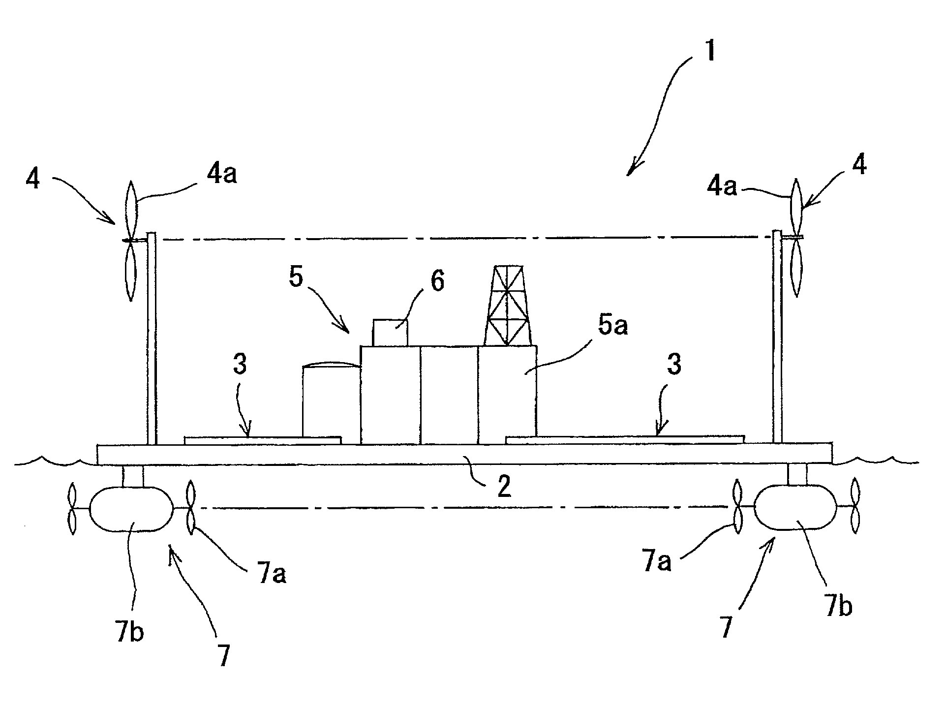
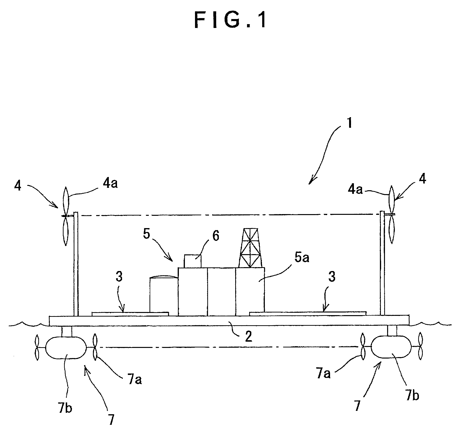
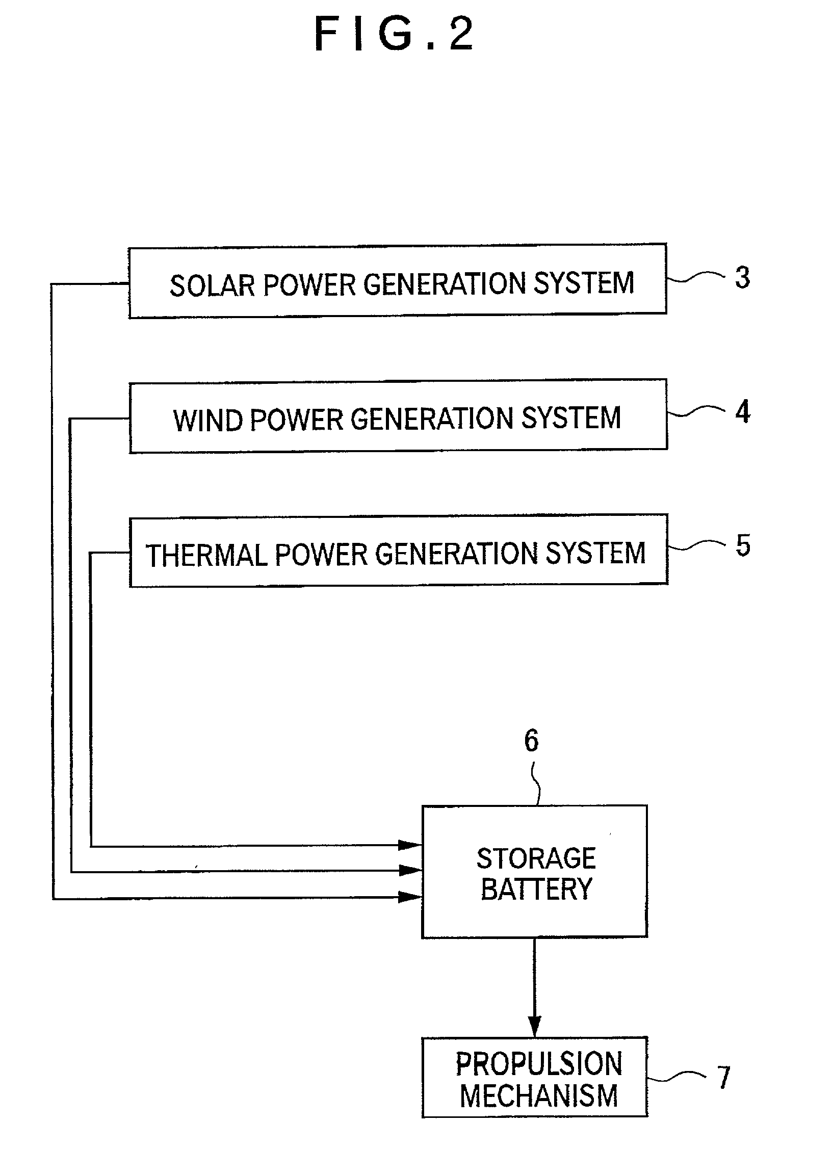
[0032] A power generation plant ship 1 according to the present embodiment of the present invention has a platform body 2 including a solar power generation system 3, a wind power generation system 4, a thermal power generation system 5, a storage battery 6, and a propulsion mechanism 7. The solar power generation system 3 has a solar battery 3a covering a wide range of the upside of the body 2 and transforming received sunlight into electric energy. The wind power generation system 4 has a plurality of windmills 4a disposed on periphery of the upside of the body 2, the windmills rotating by receiving wind force to drive a generator and generate electric energy.

[0033] The thermal power generation system 5 has thermal power generation equipment 5a provided substantially at the center of the body 2. The thermal power generation system 5 generates electric energy by driving a generator with thermal energy ...

second embodiment

[0038] Next, the present invention will be described below with reference to FIG. 4.

[0039] While the aforesaid first embodiment stores the electric energy obtained by the respective power generation systems 3, 4 and 5 in the storage battery 6, the second embodiment stores the electric energy obtained by the respective power generation systems 3, 4 and 5 after transforming into hydrogen.

[0040] Specifically, the present embodiment freshens seawater by a freshening system 9 such as seawater-freshening equipment using a method such as an ion-exchange method, and using the electric energy obtained by the solar power generation system 3, the wind power generation system 4 and the thermal power generation system 5. The fresh water is decomposed into hydrogen and oxygen by a water electrolysis system 10 such as electrolyzed hydrogen / oxygen gas producing equipment. The hydrogen is stored in a hydrogen storage 11. The hydrogen storage 11 stores the hydrogen as gas or liquid by liquid hydrogen...

third embodiment

[0041] Next, the present invention will be described below with reference to FIG. 5.

[0042] The third embodiment further includes a storage battery 6 for storing electric energy in addition to the arrangement shown in FIG. 4.

[0043] Specifically, in this embodiment, the electric energy obtained by the solar power generation system 3, the wind power generation system 4 and the thermal power generation system 5 is stored in the storage battery 6 as well as stored in the hydrogen storage 11 as energy transformed from the electric energy and stored in hydrogen.


PUM


Abstract

A power generation plant ship (1) of the present invention having a body (2) with a propulsion mechanism (7) includes a solar power generation system (3), a wind power generation system (4) for obtaining electric energy by driving a generator by rotating a windmill (4a) by receiving wind power, and a storage battery (6) for storing the electric energy generated by the respective power generation systems (3, 4).

Description

[0001] 1. Field of the Invention[0002] The present invention relates to a power generation plant ship. More specifically, it relates to a power generation plant ship which sails in accordance with seasons, weather etc. to a place where sunlight can be most effectively received or a place where wind force is strong for generating electrical power from the sunlight and the wind force etc.[0003] 2. Description of Related Art[0004] Recently, in accordance with increase in energy consumption, global environmental pollution has become a problem, and alternative energy in place of the presently used fossil fuel such as petroleum has been increasingly required.[0005] At present, as one of arts for common clean alternative energy, an art to transform solar energy into electric energy by solar battery is known. The art has been made into practical use. Further, stored hydrogen is one of expected alternative energy sources. The energy is obtained by storing compressed hydrogen gas and using th...

Claims


Application Information

Patent Timeline
Patent Type & Authority Applications(United States)
IPC IPC(8): B63B35/44B63H25/42F03D9/00F03D11/04
CPCB63B35/44B63B2035/4453B63B2035/446B63H25/42Y02E10/727F03D9/007F03D11/04F05B2240/93Y02E10/725B63J2099/005F03D13/25Y02E10/72Y02E70/30F03D9/11F03D9/22F03D9/25
Inventor TANAKA, EITARO
Owner TANAKA EITARO
Why Eureka
Try Eureka