Backup power supply

a power supply and back-up technology, applied in emergency power supply arrangements, secondary cell servicing/maintenance, transportation and packaging, etc., can solve the problems of low power conversion efficiency, high price, and large volume of power units

Inactive Publication Date: 2002-12-12
HITACHI LTD
View PDF0 Cites 85 Cited by
  • Summary
  • Abstract
  • Description
  • Claims
  • Application Information

AI Technical Summary

Problems solved by technology

However, there are many series stages of converters through which the current passes during the period from the commercial AC power supply to the load, so that the power conversion efficiency is made lower and realization of power conservation is difficult.
The aforementioned conventional backup power supply requires three converters such as the AC-DC converter, DC-DC converter, and charge circuit, so that problems arise that the price is high and the volume of the power unit is large.
However, when the charge circuit is stopped by the aforementioned operation method,

Method used


Image

  • Backup power supply
  • Backup power supply
  • Backup power supply

Examples


first embodiment

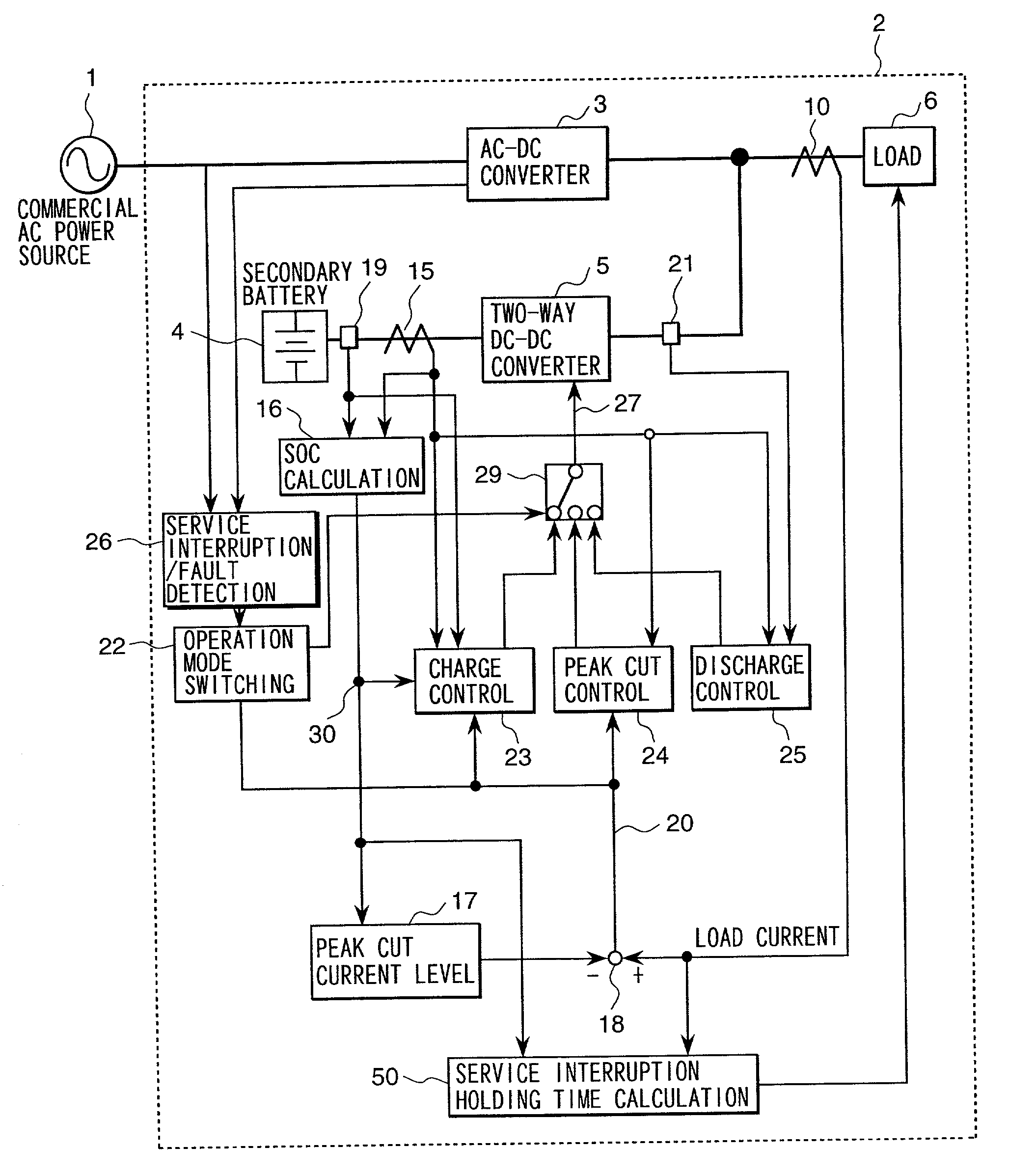
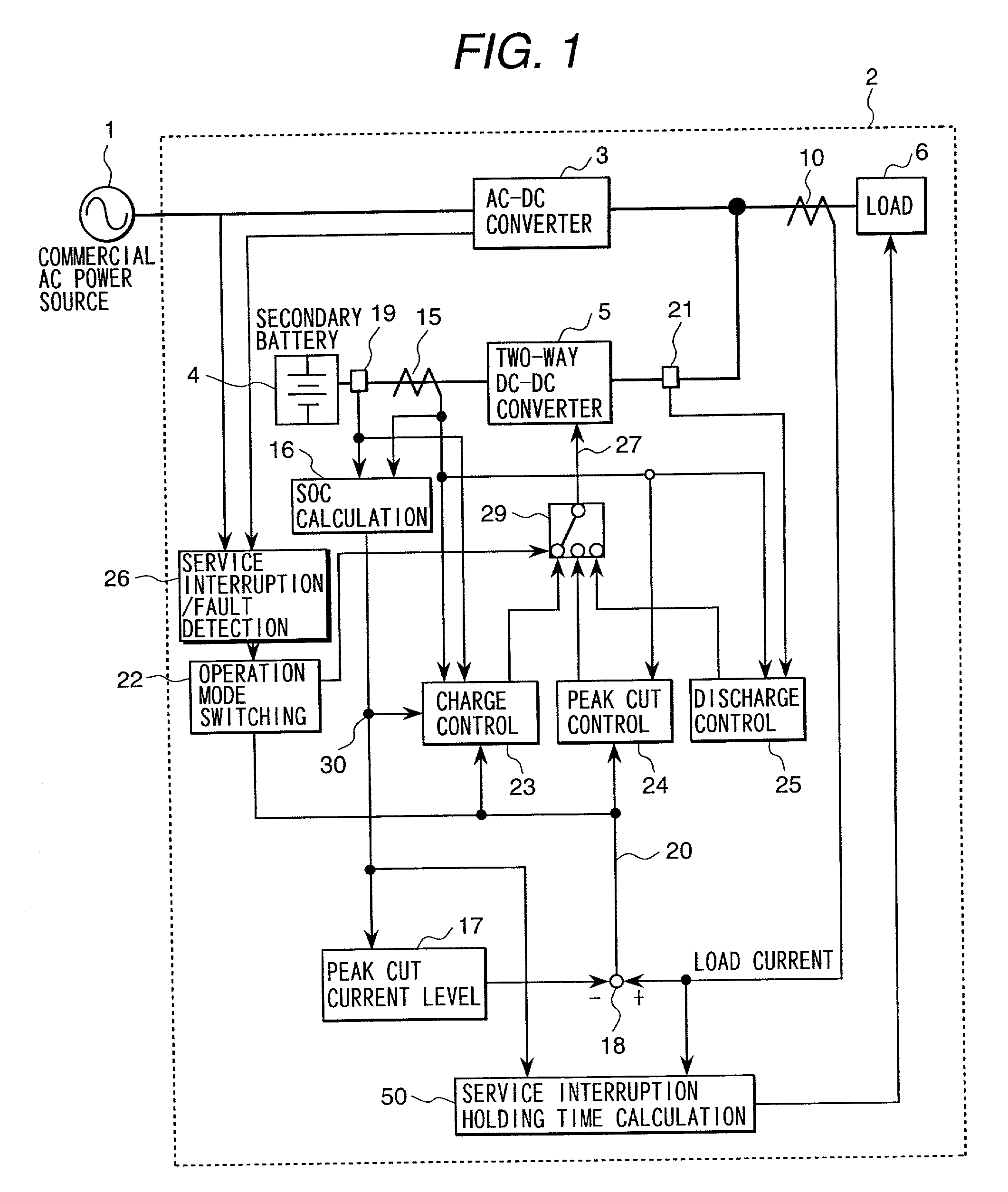
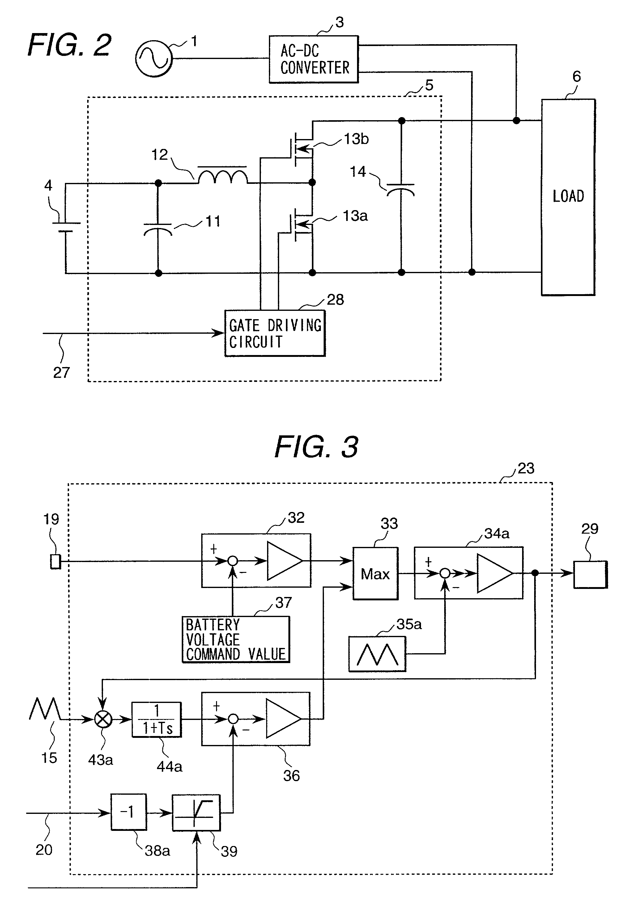
[0031] the present invention will be explained by referring to FIGS. 1 to 8. FIG. 1 is a block diagram showing an embodiment of the present invention. In FIG. 1, an information processor 2 internally has an AC-DC converter 3, a secondary battery 4, a two-way DC-DC converter 5, a load 6, a load current detector 10, a battery current detector 15, an SOC calculation circuit 16, a peak cut current level setting unit 17, a subtracter 18, a battery voltage detection means 19, an output voltage detection means 21, an operation mode switching circuit 22, a charge control circuit 23, a peak cut control circuit 24, a discharge control circuit 25, a service interruption / fault detection circuit 26, and a service interruption holding time calculation circuit 50.

[0032] A commercial AC power supply 1 is a commercial AC power supply of 100 V or 200 V and connected to the AC-DC converter 3 and the service interruption / fault detection circuit 26 installed in the information processor 2. A fault signa...

second embodiment

[0068] Next, the present invention will be explained. In FIG. 9, the same numerals are assigned to the same components as those shown in FIG. 1. Additionally, a memory 48 and a load current pattern setting unit 49 are provided. The connection configuration of the components other than the aforementioned shown in FIG. 9 is the same as that shown in FIG. 1. The memory 48 is connected to the load current detector 10 and the load current pattern setting unit 49 is connected to the memory 48. The output of the load current pattern setting unit 49 is input to the peak cut current level setting unit 17.

[0069] Next, the operation will be explained. The variation of the load current is detected by the load current detector 10 and recorded in the memory 48. For example, one day is divided every a fixed period such as every one minute or one second and load currents are sampled and stored at a predetermined address of the memory 48 as mean value data thereof. At the same time on the next day, ...


PUM


Abstract

The present invention reduces the capacity of the AC-DC converter for the peak load and realizes low price and reduction in the volume of the power unit. The apparatus built-in backup power supply has the peak cut function for sharing a part of the load current at the time of peak load from the secondary battery. The two-way DC-DC converter 5 and the secondary battery 4 are installed on the DC output side of the AC-DC converter 3 and a current larger than a predetermined peak cut level is discharged from the secondary battery 4 at the time of peak load. Further, when the load is less than the predetermined cut level, the secondary battery 4 is charged from the AC-DC converter 3 via the two-way DC-DC converter 5. Furthermore, a most suitable peak cut level according to the SOC of the secondary battery and load pattern is automatically set and dynamically changed.

Description

[0001] 1. Field of the Invention[0002] The present invention relates to a backup power supply arranged in an apparatus.[0003] 2. Prior Art[0004] Conventionally, in an apparatus operating under connection to a commercial AC power supply and in a computer suffering damage such as data loss if the commercial AC power supply fails, an uninterruptible power supply (UPS) is installed externally and a countermeasure for service interruption is taken. The UPS externally installed generally uses a fixed inverter power supply system. The fixed inverter power supply system UPS is free of the power supply switching operation at the time of service interruption and high in stability of the power supply. However, there are many series stages of converters through which the current passes during the period from the commercial AC power supply to the load, so that the power conversion efficiency is made lower and realization of power conservation is difficult.[0005] On the other hand, a backup power...

Claims


Application Information

Patent Timeline
IPC IPC(8): H02J7/00H01M10/44H02J9/06
CPCH02J9/061
Inventor KANOUDA, AKIHIKOMASUYAMA, SATORUISOGAI, MASATOSAGA, RYOUHEIONDA, KENICHITOKUNAGA, NORIKAZU
Owner HITACHI LTD
Why Eureka
Try Eureka