Supercharge Your Innovation With Domain-Expert AI Agents!

Antenna duplexer and mobile communication device using the same

a duplexer and mobile communication technology, applied in piezoelectric/electrostrictive/magnetostrictive devices, digital transmission, impedence networks, etc., can solve the problems of not being able to adapt to simultaneous transmission and reception, and the loss is larger than when the antenna switch is turned on

Inactive Publication Date: 2002-12-12
PANASONIC CORP
View PDF9 Cites 22 Cited by
  • Summary
  • Abstract
  • Description
  • Claims
  • Application Information

AI Technical Summary

Problems solved by technology

With respect to these switches, however, though miniaturization and low-loss have been realized due to a constitution having a semiconductor IC and a pin diode, they are not adaptable to simultaneous transmission and reception.
However, when the above described constitution is used in the case where a system using the frequency division system which is a simultaneous transmission and reception coexists with a system which is a non-simultaneous transmission and reception, there arose a problem that a loss becomes larger than when the antenna switch was used.

Method used


Image

  • Antenna duplexer and mobile communication device using the same
  • Antenna duplexer and mobile communication device using the same
  • Antenna duplexer and mobile communication device using the same

Examples


first embodiment

[0098] In the first embodiment, various types of composite filters which can be used as one component of the antenna duplexer to be described in a second embodiment will be described.

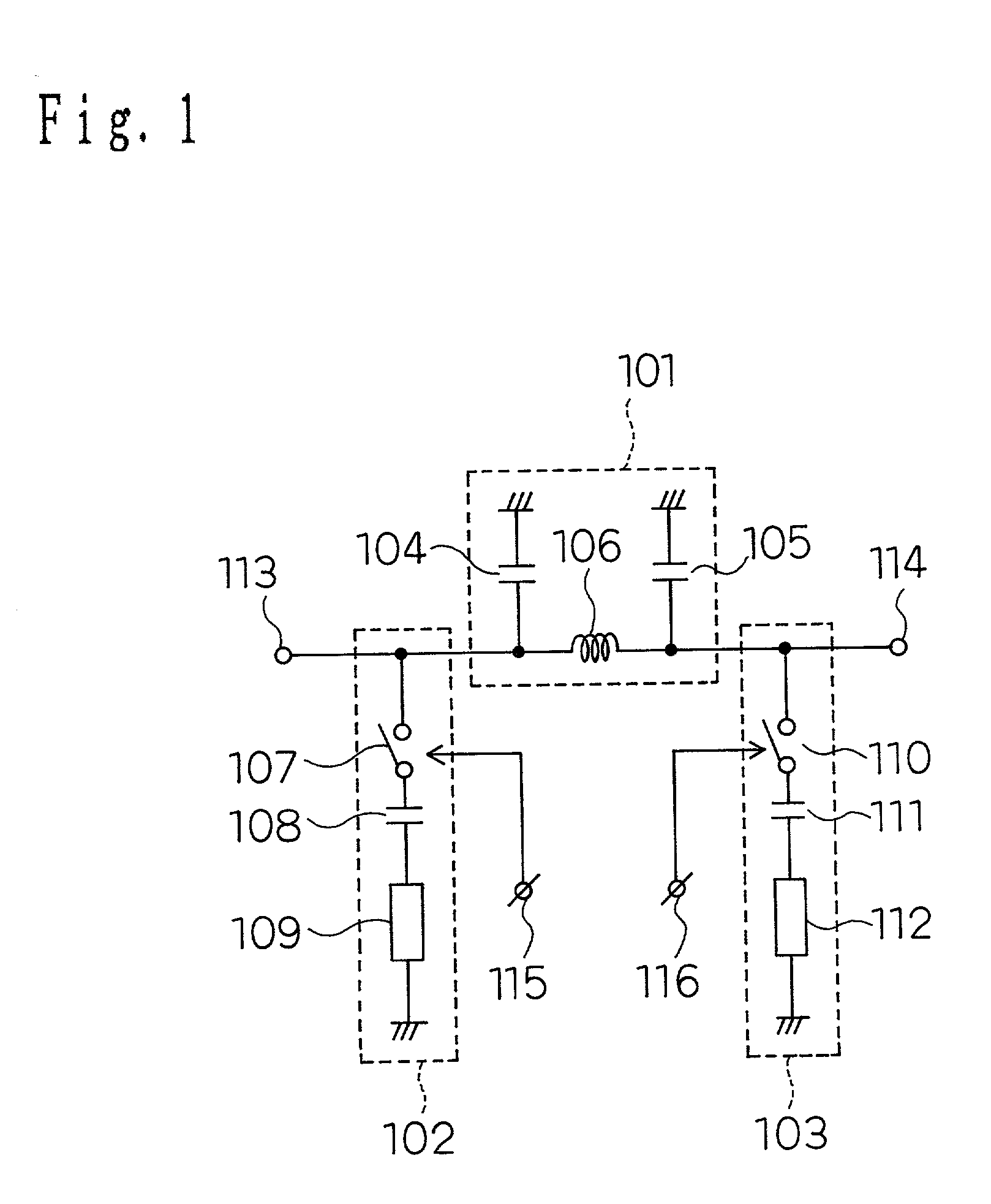
[0099] FIG. 1 shows schematically a composite filter of the first embodiment.

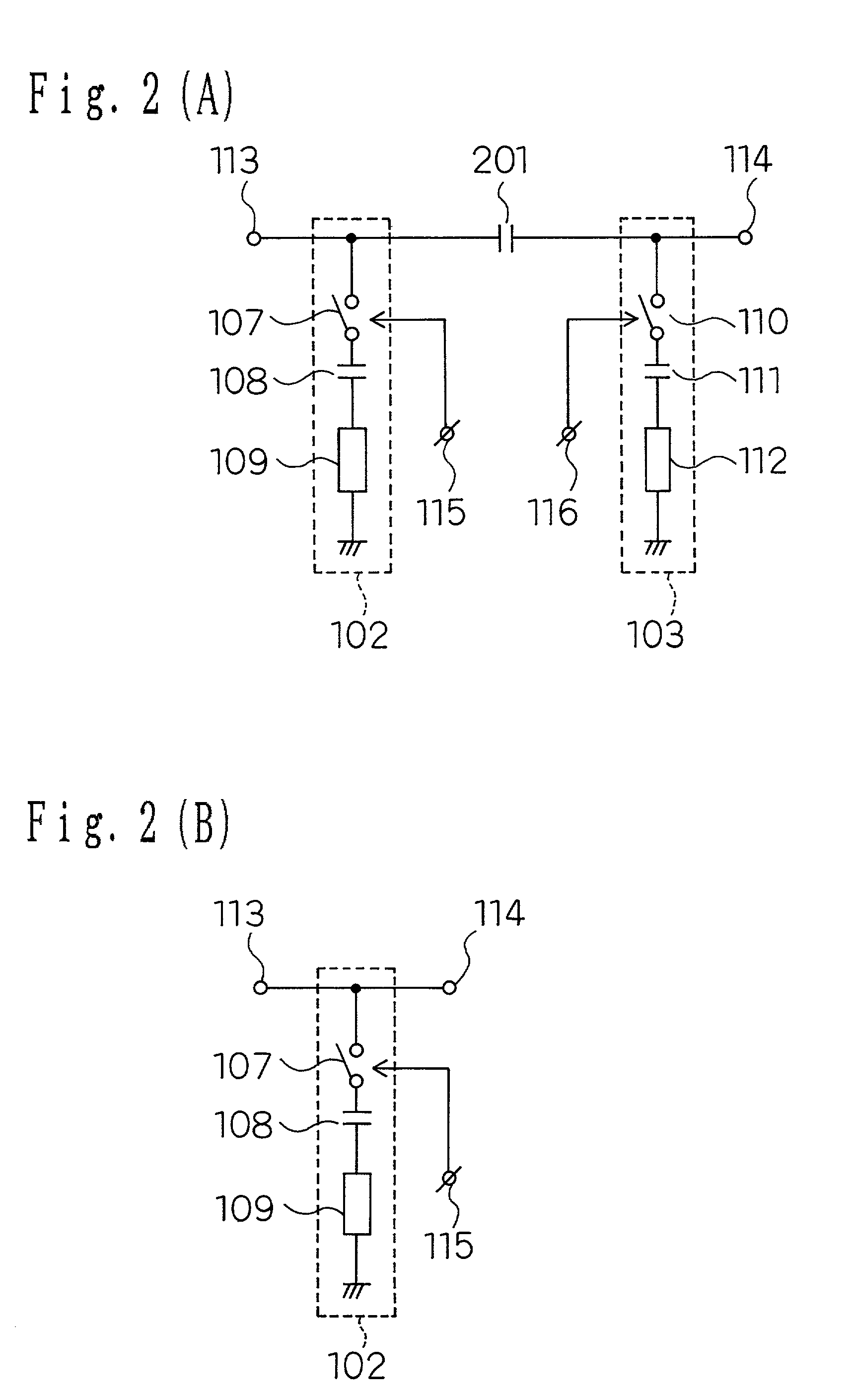
[0100] The composite filter shown in FIG. 1 is constituted by a low-pass filter 101, which is a transmitting circuit, and a first and second switching notch filters 102, 103. The low-pass filter 101 is a .pi. type circuit which is constituted by a first and a second capacitors 104, 105 and an inductor 106. Further, the first notch filter 102 is connected in series to a first switch 107, a first capacitor 108 and a first resonator 109. One end of the first resonator 108 is grounded. The second notch filter 103 is connected in series to a second switch 110, a second capacitor 111 and a second resonator 112. One end of the second resonator is grounded.

[0101] Here, the first resonator 109 is a line of .lambda. / 4 length and forms a ...

second embodiment

[0126] Hereinafter, an antenna duplexer of a second embodiment of the present invention will be described with reference to the drawings. The antenna duplexer of the second embodiment uses various composite filters described in the first embodiment as its one component.

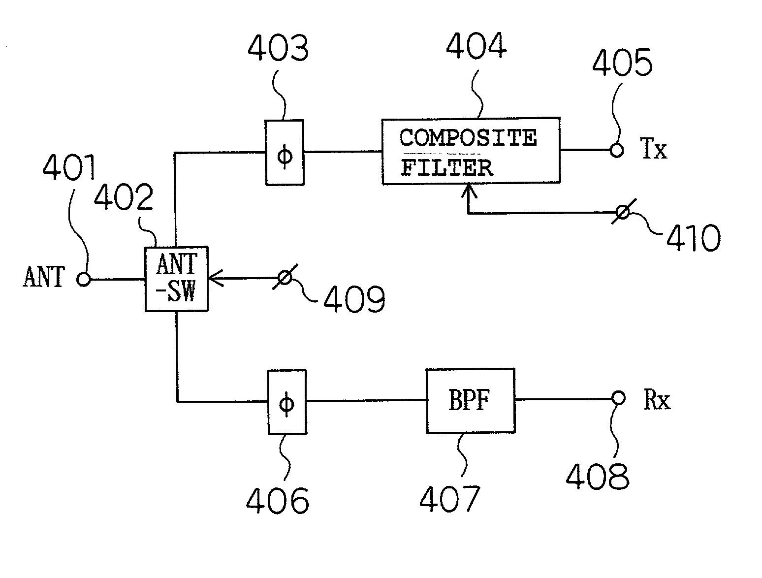
[0127] A schematic diagram of the antenna duplexer in the second embodiment is shown in FIG. 4

[0128] In FIG. 4, an antenna terminal (ANT) 401 is connected to a transmitting terminal (Tx) 405 via an antenna switch (ANT-SW) 402, a transmitting phase-shift circuit (.phi.) 403 and a composite filter 404 as a transmitting filter. Further, the antenna terminal (ANT) 401 is connected to a receiving terminal (Rx) 408 via an antenna switch 402, a receiving phase-shift circuit (.phi.) 406, a band-pass filter (BPF) 407 as a receiving filter. The antenna terminal 402 is connected with an antenna control terminal 409, which performs a switch control. Further, the composite filter 404 is connected with a control terminal 410.

[0129]...

third embodiment

[0148] Next, a constitution of an antenna duplexer of a third embodiment of the present invention will be described. Shown in FIG. 7 is a block diagram of the antenna duplexer. An antenna 701 is constituted on a laminated filter 702 comprising a dielectric by an antenna switch 703 which handles individually the transmitted and received signals, a first and a second switches 704, 705 which constitute a switching notch filter, and an surface acoustic wave filter 706 which is arranged at the receiving side. Among each layer in the interior of the laminated filter 702, there are interposed the components of a transmitting phase-shift circuit, a receiving phase-shift circuit and the switching notch filter of the transmitting side.

[0149] Further, the side surface of the laminated filter 702 is provided with an antenna terminal (ANT), a transmitting terminal (Tx) a receiving terminal (Rx), a ground terminal (GND) and a switch selector control terminal (CONT). In order to form a constitutio...


PUM


Abstract

An antenna duplexer has an antenna terminal; a transmitting phase-shift circuit, one side of which is connected to the antenna terminal; a receiving phase-shift circuit, one side of which is connected to the antenna terminal; a transmitting filter connected to the other side of the transmitting phase-shift circuit and a transmitting terminal; and a receiving filter connected to the other side of the receiving phase-shift circuit and a receiving terminal; wherein the transmitting filter and / or the receiving filter is a composite filter, and the composite filter attains a characteristic having an attenuation pole at simultaneous transmission and reception time when transmission and reception are simultaneously performed, and controls respective impedances by the transmitting phase-shift circuit and the receiving phase-shift circuit to operate as a sharing unit and attains a characteristic where the attenuation pole is removed at non simultaneous transmission and reception time when transmission and reception are not performed simultaneously.

Description

[0001] 1. Field of the Invention[0002] The present invention relates to an antenna duplexer which, for example, can handle individually a transmitted signal and a received signal of a portable telephone or the like, and to a mobile communication device.[0003] 2. Related Art of the Invention[0004] In recent years, in mobile communication devices, a frequency-division system capable of simultaneously transmission and reception has been used in systems such as CDMA and the like, and it has attracted attention from the standpoint of expansion of the transmission information content of data communications and the like. In order to make such a simultaneous transmission and reception possible, a shared antenna unit that handles individually the transmitted signal and the received signal, has been widely used. Furthermore, regarding the mobile communication devices such as portable telephones and the like, in order to realize miniaturization and high performance, miniaturization of the shar...

Claims


Application Information

Patent Timeline
Patent Type & Authority Applications(United States)
IPC IPC(8): H04B1/48H04B1/52
CPCH04B1/0057H04B1/52H04B1/48
Inventor NAKAMURA, HIROYUKIISHIZAKI, TOSHIOADACHI, HISASHISAKAKURA, MAKOTOKOSUGI, HIROAKIITOKAWA, HIROYUKINAKAMURA, TOSHIAKI
Owner PANASONIC CORP
Features
  • R&D
  • Intellectual Property
  • Life Sciences
  • Materials
  • Tech Scout
  • Unparalleled Data Quality
  • Higher Quality Content
  • 60% Fewer Hallucinations
Learn More