
Metal capacitor in damascene structures

a damascene and metal capacitor technology, applied in capacitors, semiconductor devices, semiconductor/solid-state device details, etc., can solve the problems of increasing overall fabrication costs, uneven surface, and aluminum used to fabricate traditional interconnections cannot meet the present-day requirements for enhanced integration and data transmission speed

Inactive Publication Date: 2002-12-19
UNITED MICROELECTRONICS CORP
View PDF0 Cites 16 Cited by
  • Summary
  • Abstract
  • Description
  • Claims
  • Application Information

AI Technical Summary

Problems solved by technology

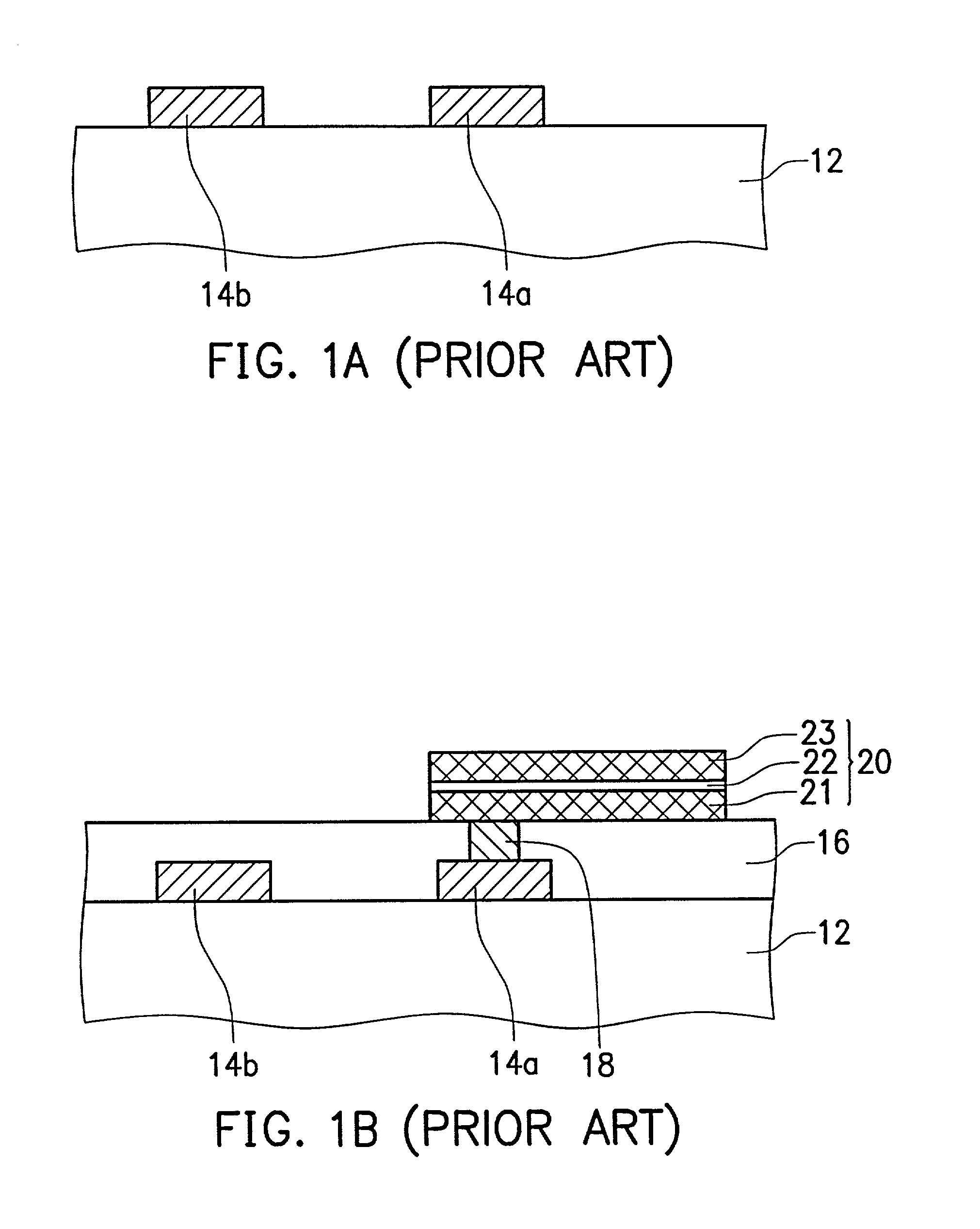
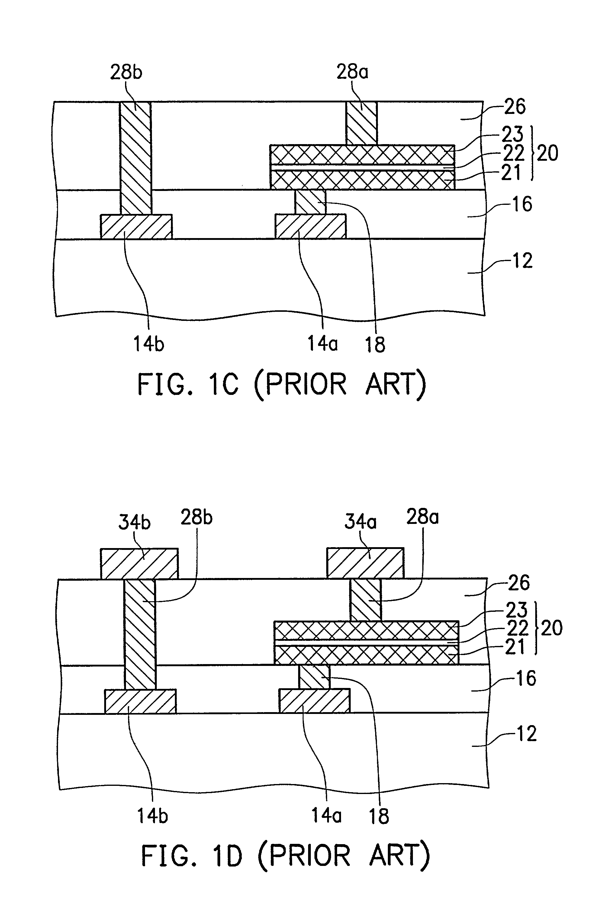
The above-mentioned traditional processes for integrating the capacitor 20 into an integrated circuit require several masking and etching steps to form the capacitor 20, which may increase overall fabrication costs.
As well, the aluminum used to fabricate the traditional interconnections cannot satisfy present-day requirements for enhanced integration and highly demanding speeds of data transmission.
The use of copper in the conductive wires requires the use of processes, that is, damascene processes, because copper cannot be patterned by etching.
However, a chemical mechanical polishing process is required to remove undesired metal residue to form the lower electrode.
Dishing is likely to occur on the lower electrode and result in an uneven surface.
Therefore, the thickness of the insulator can not be kept uniform to stabilize the electrical properties of the capacitors.

Method used


Image

  • Metal capacitor in damascene structures
  • Metal capacitor in damascene structures
  • Metal capacitor in damascene structures

Examples


Embodiment Construction

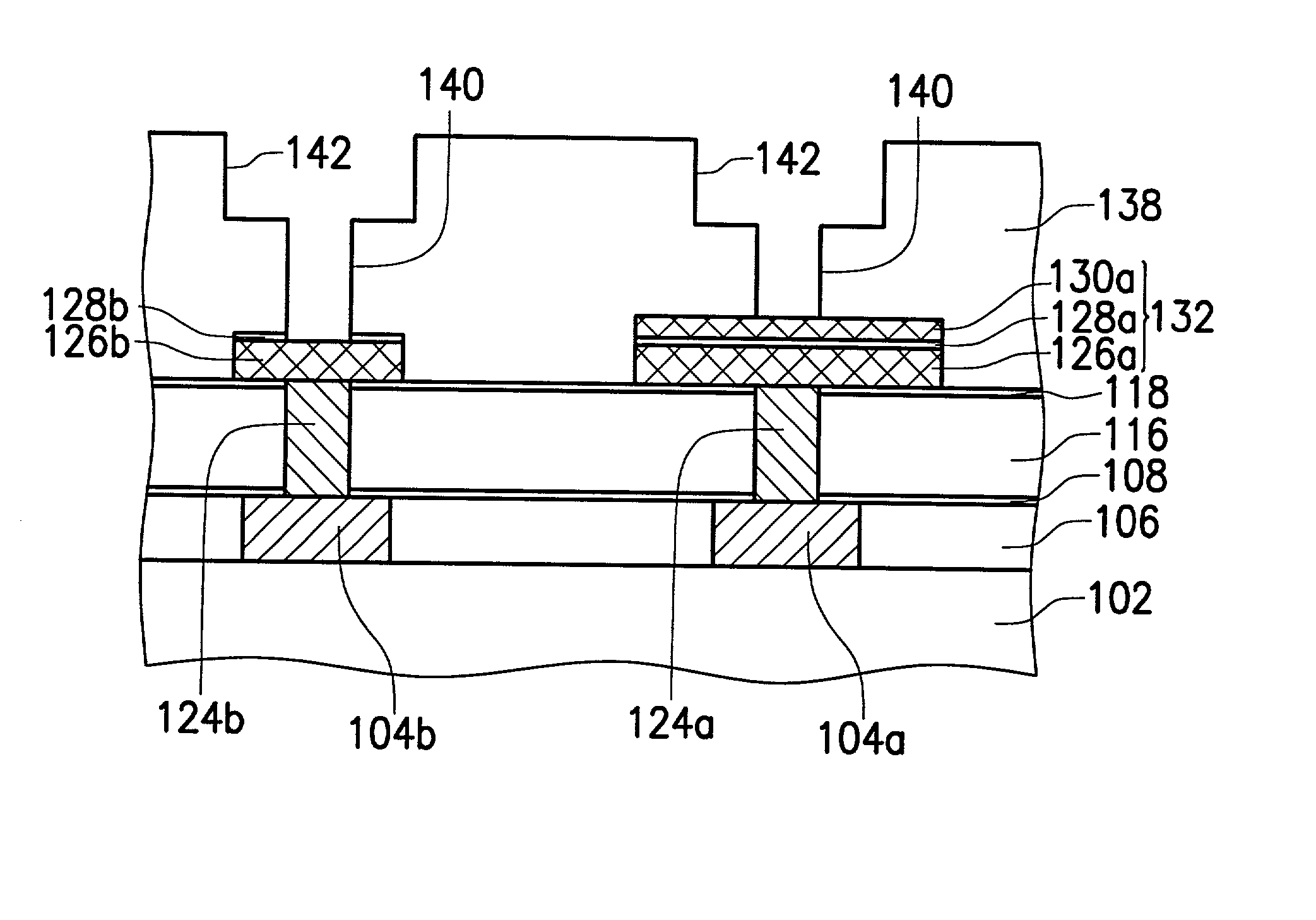
[0017] A method for forming a metal capacitor in a damascene process according to the first embodiment of the present invention is described below with reference to FIGS. 2A.about.2L.

[0018] Referring to FIG. 2A, the insulator 106 is formed on the insulator 102. The insulator 102 may include interconnections, and the insulator 102 is formed on a substrate, for example silicon semiconductor substrate, which includes numerous devices thereon and therein. The particular designs of the underlying integrated circuit have not been shown in order to highlight the various aspects of the present invention. Copper wires 104a and 104b, preferably about 2,000.about.6,000 .ANG., are formed in the insulator 106 by a damascene process. For example, first, trenches are formed in the insulator 106, and the barrier layer (not shown) is conformally formed on the insulator 106. After copper metal is formed on the barrier layer and fills in the trenches, a chemical mechanical polish process is executed t...


PUM


Abstract

A metal capacitor in damascene structures is provided. A first Cu wire and a second Cu wire are located in a first insulator. A first sealing layer is located on the first and the second Cu wires. A second insulator is located on the first sealing layer. A third insulator is located on the second insulator, and acting as an etch stop layer. A first Cu plug and a second Cu plug are located in the first sealing layer, the second insulator and the third insulator. A capacitor is located on the third insulator and the first Cu plug, the capacitor having an upper electrode, a capacitor dielectric and a bottom electrode with the same pattern each other, wherein the bottom electrode is connected to the first Cu wire through the first Cu plug. A conducting wire is located on the third insulator and the second Cu plug, wherein the conducting wire is connected to the second Cu wire through the second Cu plug. A fourth insulator is located on the conducting wire. A fifth insulator with a flat surface is located on the upper electrode, the fourth insulator and the third insulator. A plurality of dual damascene structures including a third plug, a fourth Cu plug, a third Cu wire and a fourth Cu wire are located in the fifth insulator, wherein an upper electrode of the capacitor is connected to the third Cu wire through the third Cu plug, and the conducting wire is connected to the fourth Cu wire through the fourth Cu plug. A second sealing layer is located on the third and fourth Cu wires.

Description

[0001] This application is a continuation-in-part of U.S. application Ser. No. 09 / 881,102, filed Jun. 15, 2001, now allowed.[0002] 1. Field of the Invention[0003] The present invention relates in general to an integrated circuit including capacitors. In particular, the present invention relates to a metal capacitor in damascene structures.[0004] 2. Description of the Related Art[0005] Capacitors are deployed in various integrated circuits. For example, decoupling capacitors provide improved voltage regulation and noise immunity for power distribution. Capacitors also have wide applications in analog / logic, analog-to-digital, mixed signal, radio frequency circuit operations, and others.[0006] A conventional method of manufacturing a semiconductor apparatus including a capacitor 20 that is formed of metal-insulator-metal layers is described with reference to FIGS. 1A.about.1D. As shown in FIG. 1A, an aluminum layer is deposited on an insulator 12 which contains interconnections and is...

Claims


Application Information

Patent Timeline
Patent Type & Authority Applications(United States)
IPC IPC(8): H01L21/02H01L21/768
CPCH01L21/76801H01L28/55H01L21/76838H01L21/76807
Inventor HSUE, CHEN-CHIULEE, SHYH-DARTSAI, JEN-HANN
Owner UNITED MICROELECTRONICS CORP
Learn More