Polarizer and optical device using the polarizer

a technology of optical devices and polarizers, applied in the field of polarizers, can solve problems such as light transmission failure, weak polarizers, and failure to conduct appropriate polarization conversion

Inactive Publication Date: 2002-12-19
SEIKO EPSON CORP
View PDF9 Cites 29 Cited by
  • Summary
  • Abstract
  • Description
  • Claims
  • Application Information

AI Technical Summary

Problems solved by technology

However, since such conventional polarizer is made of organic material, the polarizer is weak against high temperature and is decolorized after continuous use in an environment of more than 70.degree. C. to lose polarizing function.
However, since such structural birefringent polarizer absorbs a part of the incident light beam on the birefringent portion, the glass substrate is distorted on account of heat, thus failing to conduct appropriate polarization conversion.
Especially, when the glass substrate is disposed on the light emission-side, the polarization axis of the polarized light beam converted by the birefringent portion is revolved in the glass substrate, thereby causing light transmission failure where a part of the light does not pass through the glass substrate.
As described above, since the birefringent portion is constructed by arranging metal concave treads such as aluminum in stripe, the concave treads can be deteriorated under high temperature and high humidity.
When the substrate surfaces of the protection plate and the base plate are entirely bonded by the elastic adhesive, the space between the concave treads of the birefringent portion is buried by the elastic adhesive, so that light diffraction ability of the birefringent portion is deteriorated, thus lowering polarization conversion efficiency.

Method used


Image

  • Polarizer and optical device using the polarizer
  • Polarizer and optical device using the polarizer
  • Polarizer and optical device using the polarizer

Examples


first embodiment

[0060] [First Embodiment]

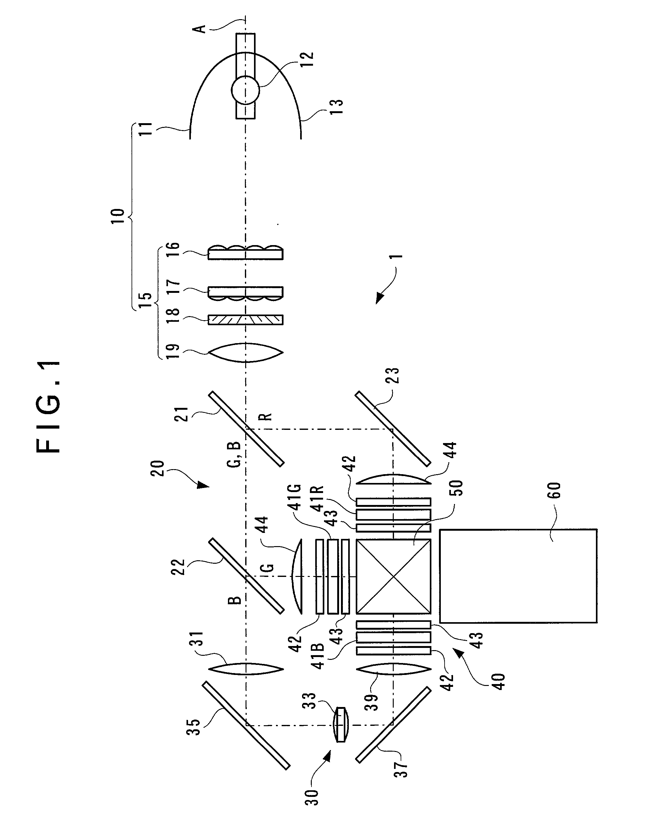
[0061] FIG. 1 is a schematic view showing a structure of an optical system of a projector 1 as the optical device according to the present invention. The projector 1 has an integrator illuminating optical system 10, a color separating optical system 20, a relay optical system 30, an electric optical device 40, a cross dichroic prism 50 as a color combining optical system and a projection lens 60 as a projection optical system.

[0062] The integrator illuminating optical system 10 has a light source 11 and a uniform illuminating optical system 15. The light source 11 is composed of a light source lamp 12 such as metal halide lamp and high-pressure mercury lamp, and a parabolic reflector 13 for aligning and parallelizing the direction of the light beam emitted from the light source lamp 12.

[0063] The uniform illuminating optical system 15 separates the light beam emitted by the light source 11 into a plurality of sub-beams and aligns the polarization direction o...

second embodiment

[0099] [Second Embodiment]

[0100] Next, second embodiment of the present invention will be described below. Incidentally, in the following description, the same reference numeral will be attached to the same component as described above, thereby omitting description thereof.

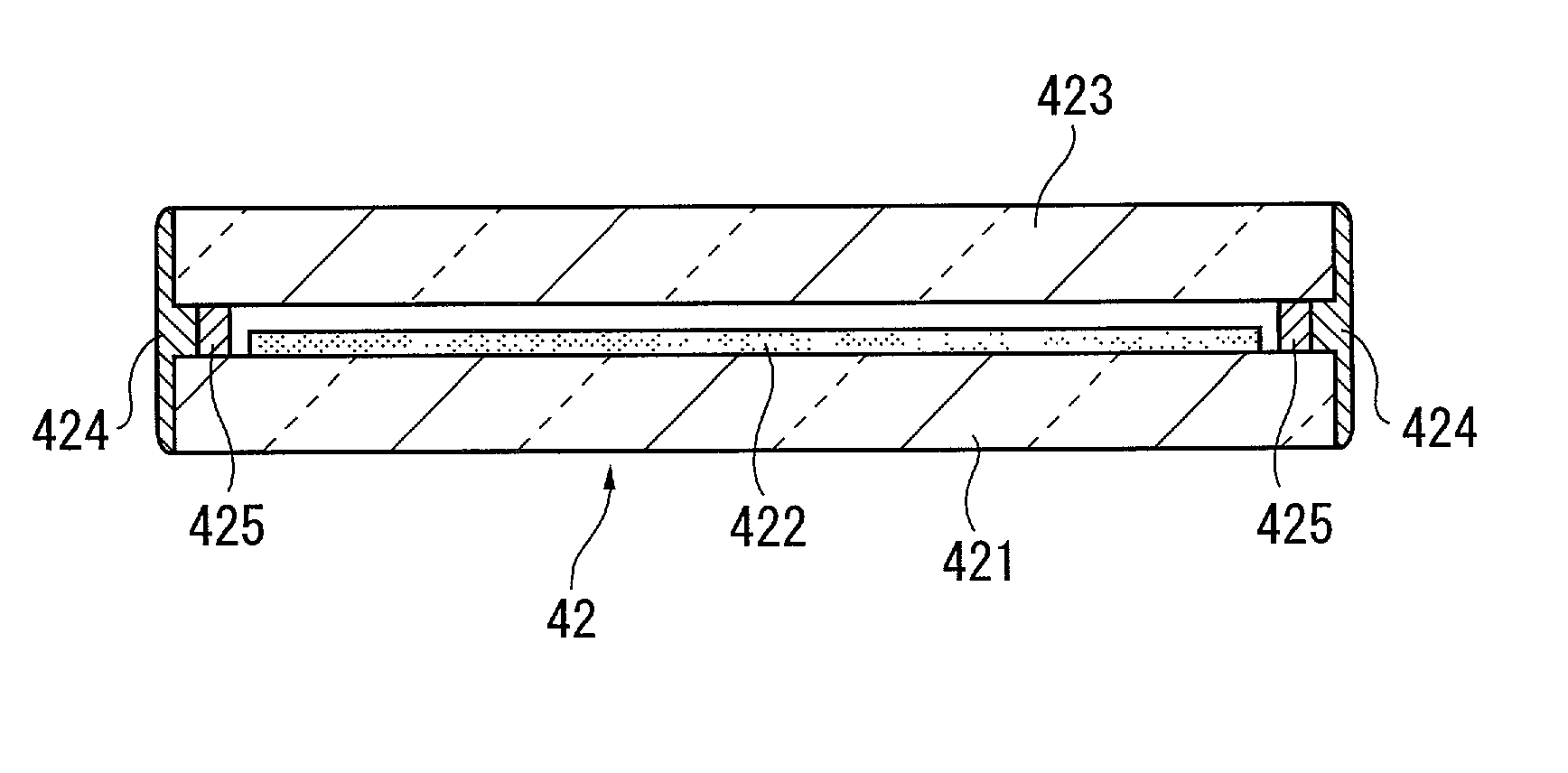
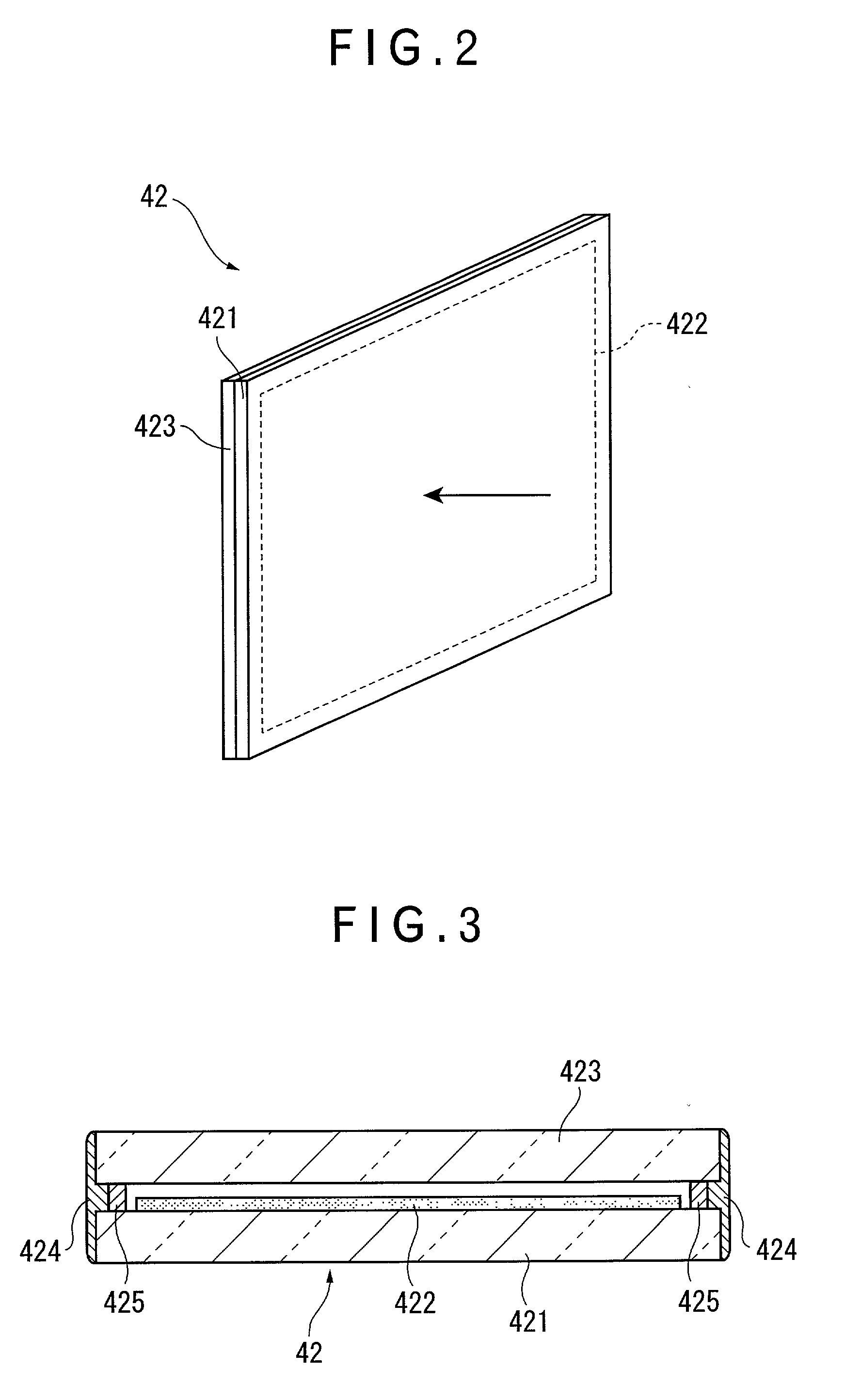
[0101] The polarization plate 42 according to the first embodiment has the protection plate 423 of approximately the same shape as the base plate 421 and the periphery of the both of the plates 421 and 423 is bonded by the silicone adhesive 424.

[0102] In contrast, a polarization plate 52 according to the second embodiment is different in that a protection plate 523 is greater than a base plate 521 as shown in FIGS. 6 and 7.

[0103] The base plate 521 and the protection plate 523 are bonded by the silicone adhesive 424 at the periphery of the base plate 521 and the front surface of the protection plate 523. The amount of the silicone adhesive 424 can be set in any manner by increasing the coating amount on the protec...

third embodiment

[0112] [Third Embodiment]

[0113] Net, third embodiment of the present invention will be described below.

[0114] As shown in FIGS. 8 and 9, a polarization plate 62 of the third embodiment is similar to the polarization plate 52 of the second embodiment in that the size of protection plate 623 is greater than the size of base plate 621 and the respective plates are made of sapphire. However, the polarization plate 62 is different from the polarization plate 52 in that a spacer 625 interposed between the base plate 621 and the protection plate 623 is double-sided tape.

[0115] The spacer 625 is provided along the entire circumference of the birefringent portion 422 and is stuck from the protection plate 623 side of the birefringent portion 422 to the light-emission side of the base plate 621. By disposing the protection plate 623 on the spacer 625, the protection plate 623 and the birefringent portion 422 are spaced apart with a predetermined gap.

[0116] Though not shown, a first side abutt...


PUM

PropertyMeasurementUnit
light transmittanceaaaaaaaaaa
thermal conductivityaaaaaaaaaa
temperatureaaaaaaaaaa

Abstract

A polarizer for converting incident light beam into a linear polarization light beam has a base plate of a material of low linear expansion coefficient, high thermal conductivity or low photoelastic constant, a birefringent portion formed by arranging minute metal concave tread on a surface of light-emission side of the base plate in stripe, and a protection plate covering the birefringent portion and made of the same material as the base plate, the base plate and the protection plate being bonded by an elastic adhesive on the periphery thereof so that the birefringent portion is sealed and enclosed by the protection plate and the elastic adhesive.

Description

[0001] 1. Field of the Invention[0002] The present invention relates to a polarizer for converting incident light beam into a linear polarization beam and an optical device using the polarizer.[0003] 2. Description of Related Art[0004] Conventionally, a projector having a light source, an electric optical device for modulating the light beam irradiated by the light source in accordance with image information, and a projection optical system for enlarging and projecting the light beam modulated by the electric optical device has been used as an optical device using the electric optical device.[0005] Liquid crystal device is known as the electric optical device, which includes an electric optical element having a pair of transparent substrates between which electric optical material such as liquid crystal is sealed and enclosed, and two polarization plates as a polarizer disposed on the light-incident side and light-emission side of the electric optical device.[0006] In a conventional...

Claims


Application Information

Patent Timeline
Patent Type & Authority Applications(United States)
IPC IPC(8): G02B5/30G02F1/13G02F1/1335G03B21/00
CPCG02B5/3083G02B5/3025
Inventor MIYAZAWA, ATSUSHIHASHIZUME, TOSHIAKI
Owner SEIKO EPSON CORP
Why Eureka
Try Eureka