Post injections during cold operation

a post-injection and cold-operation technology, applied in the direction of electrical control, machines/engines, mechanical equipment, etc., can solve the problems of increasing the complexities and costs of electrical and exhaust systems, failing to take into account the effects of secondary injection on fuel economy, engine durability, injector durability and fuel dilution, and 775 patents that do not control secondary fuel injection

Inactive Publication Date: 2002-12-26
FORD MOTOR CO +1
View PDF0 Cites 38 Cited by
  • Summary
  • Abstract
  • Description
  • Claims
  • Application Information

AI Technical Summary

Benefits of technology

0012] In one aspect of the present invention there is disclosed an exhaust gas heating system of a direct injection compression ignition internal combustion engine which has a plurality of combustion chambers and an exhaust passage, and one or more direct fuel injection devices, each operable to inject fuel directly into a corresponding one of the combustion chambers. The system also includes a fuel injection controller which is operable to provide to at least one of the direct fuel injection dev

Problems solved by technology

However, the current technology of NOx catalysts requires a sufficient concentration of a reducing agent, usually a hydrocarbon (HC) compound, to be present in the exhaust gas at the catalyst.
Unfortunately, the direct heating of the catalyst in this fashion substantially increases both electrical and exhaust system complexities and costs while failing to achieve optimum activation of the catalyst.
Previous secondary injection systems which inject additional fuel into the engine to create additional heating of the exhaust have failed to take into account the effects of secondary injections on fuel economy, engine durability, injector durability and fuel dilution of engine oil.
The '775 patent does not control secondary fuel injection in order to address issues related to engine durability and fuel economy.
However, neither the '775 patent or the `275 patent particularly address varying such a secondary (sub) injection to improve emissions, improve engine and injector durability and improve fuel economy.
Nor do the `775 and `275 patents address introducing such a secondary injection gradually in order to alleviate torque/mechanical energy produced by such an injection, which may cause problems in governing fuel and/or engine speed.
Under the more restrictive emissions

Method used


Image

  • Post injections during cold operation
  • Post injections during cold operation
  • Post injections during cold operation

Examples


Embodiment Construction

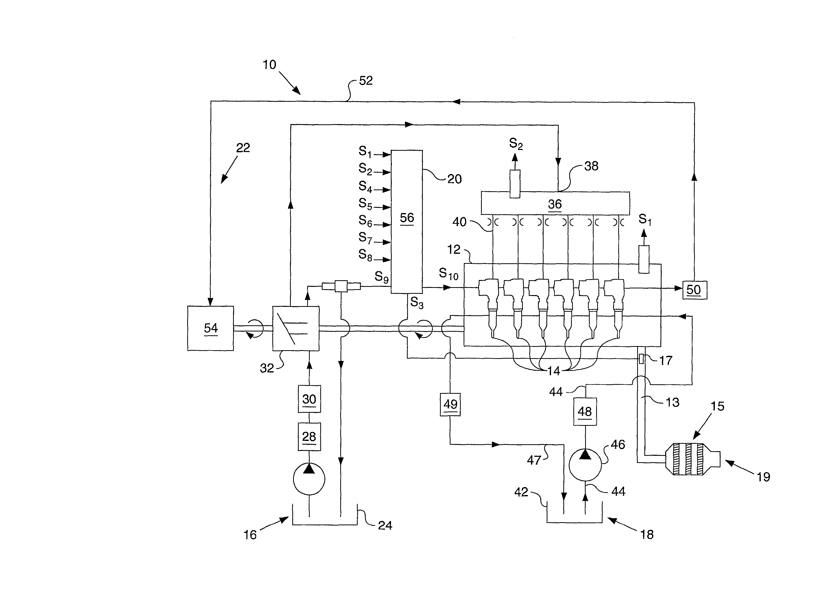
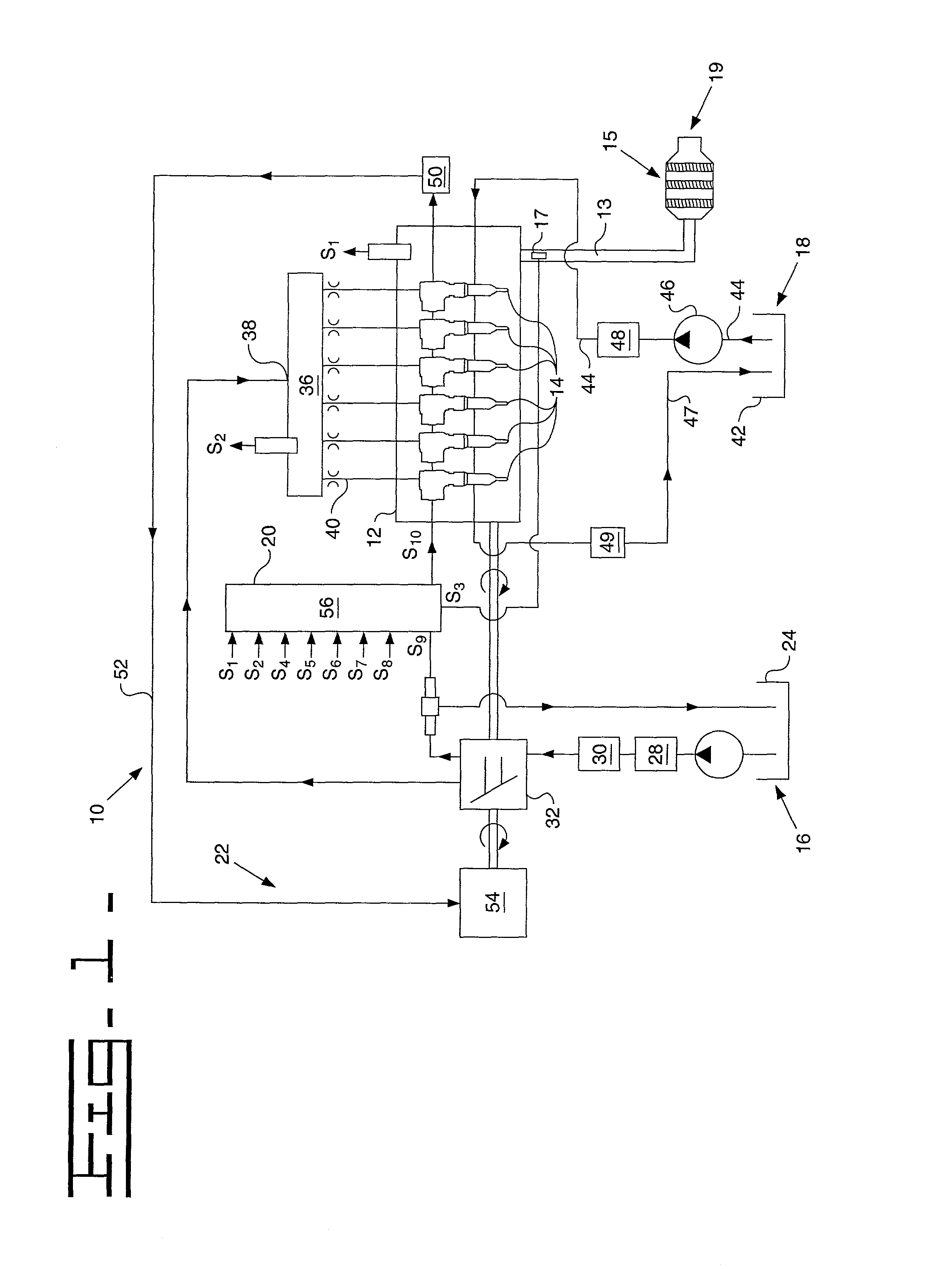
[0021] Referring to FIG. 1, there is shown one embodiment of a hydraulically actuated electronically controlled fuel injection system 10 in an exemplary configuration as adapted for a direct-injection compression ignition engine 12, preferably having a fixed compression ratio. The present invention applies to direct-injection compression ignition engines capable of running at any engine speeds, including low, medium, high, and very high engine speeds. Very high engine speeds includes engines running at 4000 rpm and above. At present, the invention finds an important application in relation to lean burn diesel engines, such as Caterpillar C-9 series and 3500 series diesel engines; however, the present invention is applicable to all internal combustion engines including four-cycle and two-cycle designs.

[0022] Fuel system 10 includes one or more electronically controlled fuel injection devices, illustrated as fuel injectors 14 in this embodiment, which are adapted to be positioned in a...


PUM


Abstract

An exhaust gas heating system and method of a direct injection compression ignition internal combustion engine which has a plurality of combustion chambers, an exhaust passage, and one or more direct fuel injection devices, each operable to inject fuel directly into a corresponding one of the combustion chambers. The system also includes a fuel injection controller which is operable to provide to at least one of the direct fuel injection devices, a post fuel injection signal during a corresponding cylinder cycle of the corresponding one of the plurality of combustion chambers. The post fuel injection signal is timed so as to provide exhaust gas heating from a resultant post fuel injection, and the fuel injection controller dynamically determines the particular one or more of the plurality of direct fuel injection devices to which the post fuel injection signal will be applied based on a temperature related engine operating parameter such as a desired amount of exhaust gas heating. The post fuel injection may also be timed and/or shaped such that it does not produce a substantial amount of mechanical energy but instead produces heated exhaust gasses.

Description

TECHNICAL FIELD[0001] This invention relates generally to electronically controlled fuel injection systems and, more particularly, to a method and apparatus for delivering multiple fuel injections to the cylinder of an internal combustion engine during a fuel injection event including a post fuel injection, based upon engine operating conditions.BACKGROUND[0002] Electronically controlled direct fuel injection devices such as electronically controlled fuel injectors are well known in the art including both hydraulically actuated electronically controlled fuel injectors as well as mechanically actuated electronically controlled fuel injectors. Electronically controlled fuel injectors typically inject fuel into a specific engine cylinder as a function of an electronic fuel injection signal received from an electronic fuel injection control device (controller). These signals include waveforms that are indicative of a desired injection rate as well as the desired timing and quantity of f...

Claims


Application Information

Patent Timeline
IPC IPC(8): F01N3/20F02B3/06F02D41/02F02D41/38F02D41/40
CPCF01N3/2006F02B3/06F02D41/0245F02D41/1446F02D41/3827Y02T10/26F02D41/405F02D2041/389F02D2250/11Y02T10/44F02D41/402Y02T10/12Y02T10/40
Inventor FLUGA, ERIC C.MCGEE, BRIAN G.KOSHKARIAN, KENT A.
Owner FORD MOTOR CO
Why Eureka
Try Eureka