Method for running up a gas turbine plant

a gas turbine and plant technology, applied in the ignition of turbine/propulsion engines, engine starters, lighting and heating apparatus, etc., can solve the problems of significant nitrogen oxide formation, unfavorable emission values, and appreciably less stable than burners operated

Inactive Publication Date: 2002-12-26
ANSALDO ENERGIA IP UK LTD
View PDF5 Cites 8 Cited by
  • Summary
  • Abstract
  • Description
  • Claims
  • Application Information

AI Technical Summary

Problems solved by technology

When this is carried out with a high air excess, relatively low flame temperatures are obtained and there is therefore an insignificant formation of nitrogen oxides.
The burners operated in this way are distinguished by a very stable flame with a high flame temperature, which, on the other hand, however, also entails unfavorable emission values.
However, they are appreciably less stable than burners operated in the pilot mode.
When a gas turbine of the type initially mentioned is run up from the idling mode into the load mode, undesirable effects often arise.
Inter alia, in particular phases of the run-up and in the part-load mode, that is to say during the pilot mode, a pronounced generation of smoke and nit

Method used


Image

  • Method for running up a gas turbine plant
  • Method for running up a gas turbine plant

Examples


Embodiment Construction

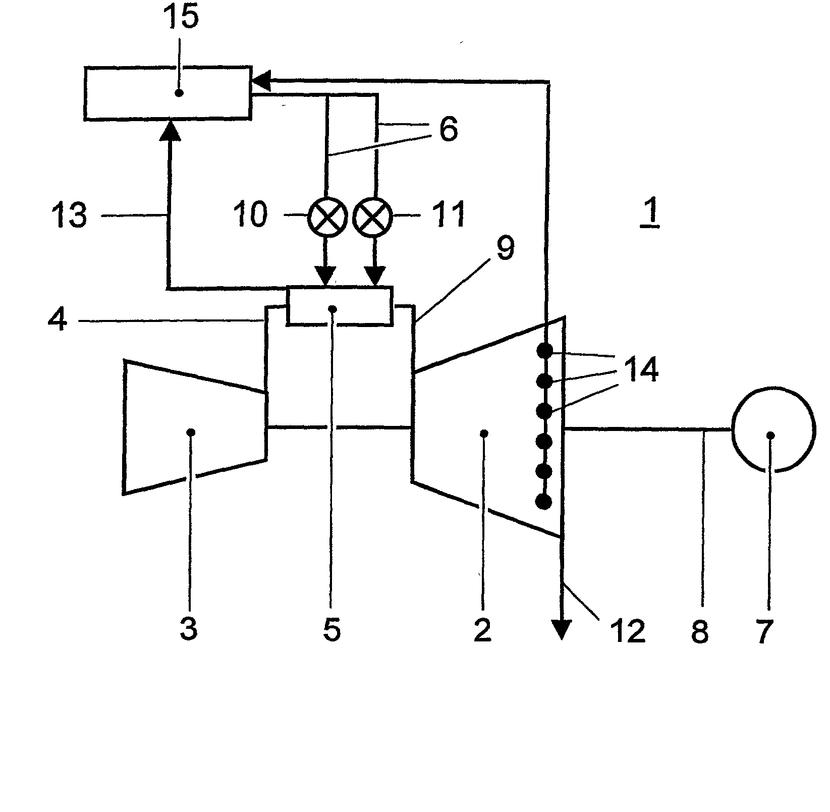
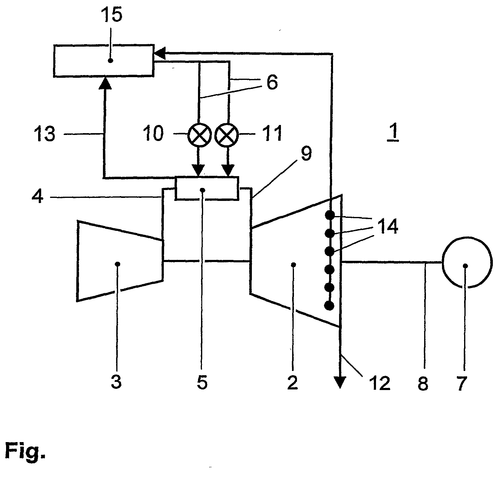
[0021] A method for running up a gas turbine plant 1, such as is illustrated, for example, in the single FIGURE, is disclosed. A fuel 6 is burnt, together with compressed air 4 coming from a compressor 3, in a combustion chamber 5 of the gas turbine plant 1. The combustion chamber 5 is designed as an annular combustion chamber, as is known from the prior art. The hot combustion gases 9 occurring in this case are led through a gas turbine 2 and the exhaust gases 12 are thereafter discharged in a known way. The gas turbine 2 is connected both to the compressor 3 and to a generator 7 via a shaft 8.

[0022] In the method according to the invention, the fuel 6 is injected into the combustion chamber 5 via a plurality of pilot burners 10 and premix burners 11. The gas turbine plant 1 is run up, in a first step, at a specific load gradient .DELTA.L, the combustion chamber 5 being operated in the pilot mode by the pilot burners 10 during ignition and in a lower load range, and the combustion ...


PUM


Abstract

A method for running up a gas turbine plant (1) is disclosed. In the method, a fuel (6) is injected into the combustion chamber (5) via a plurality of pilot burners (10) and premix burners (11). During the start-up and in a lower load range, the combustion chamber (5) is operated in the pilot mode, and, at a specific time point, the combustion chamber (5) is changed over from the pilot mode to the premix mode. The changeover time point from the pilot mode to the premix mode depends on a variable changeover temperature (TSWO), and this changeover temperature (T-SWO) is determined from pulsations occurring in the flame of the combustion chamber (5).

Description

[0001] The present invention relates to a method for running up a gas turbine plant according to the preamble of claim 1.PRIOR ART[0002] Gas turbines are increasingly equipped with multiple burners employing the lean premix technique. In this case, the fuel and the combustion air are premixed as uniformly as possible and only then fed to the flame. When this is carried out with a high air excess, relatively low flame temperatures are obtained and there is therefore an insignificant formation of nitrogen oxides.[0003] In accordance with the geometry of gas turbines, the plurality of burners are often arranged annularly in the form of annular combustion chambers. Such annular gas turbine combustion chambers are known, for example, from EP-B1-0 597 138, U.S. Pat. Nos. 4,100,733, 5,303,542, 5,402,634, EP-A2-802,310 or EP-A1-976,982. The liquid or gaseous fuels are in this case fed via fuel feed rings to the burners arranged in single and multiple rings, where they are injected into the ...

Claims


Application Information

Patent Timeline
IPC IPC(8): F02C7/228F02C9/34F02C7/26F02C9/28F23R3/30F23R3/34
CPCF02C9/28F02C7/26
Inventor STALDER, MARCELREBHAN, DIETERKUEENZI, THOMASKNOEPFEL, HANS PETER
Owner ANSALDO ENERGIA IP UK LTD
Why Eureka
Try Eureka