Flatted object passive aligner

a technology for flatted objects and aligners, which is applied in the direction of charging manipulation, lighting and heating apparatus, furniture, etc., can solve the problems of positioning error, high price of active alignment devices, and large active alignment devices that use motors

Inactive Publication Date: 2002-12-26
NOVELLUS SYSTEMS
View PDF0 Cites 13 Cited by
  • Summary
  • Abstract
  • Description
  • Claims
  • Application Information

AI Technical Summary

Benefits of technology

0017] It is preferred that all the rollers turn freely so that the flatted object will automatically and passively align itself to the desired position and rotational orientation under the influence of gravity. However, one or more of the rollers may be motorized, if desired, with sensors employed to detect when the desired orientation has been achieved.

Problems solved by technology

However, active alignment devices are expensive.
Active alignment devices that use motors are also relatively large.
Although the wafers can be pre-aligned before they are moved into a processing system, the PEC cover is often stored internally where there is limited space available.
Although the transport mechanism can accurately position a pre-aligned wafer or PEC cover on the chuck, each time the object is picked up and set down there is some positioning error.
This positioning error can build up to unacceptable levels for a PEC cover that is repeatedly handled if it is not aligned between uses.
Consequently, a large active alignment mechanism that is suitable for pre-aligning wafers before entering the processing system may not be suitable for a PEC cover stored internally that must be repeatedly handled and repositioned accurately.

Method used


Image

  • Flatted object passive aligner
  • Flatted object passive aligner

Examples


Embodiment Construction

)

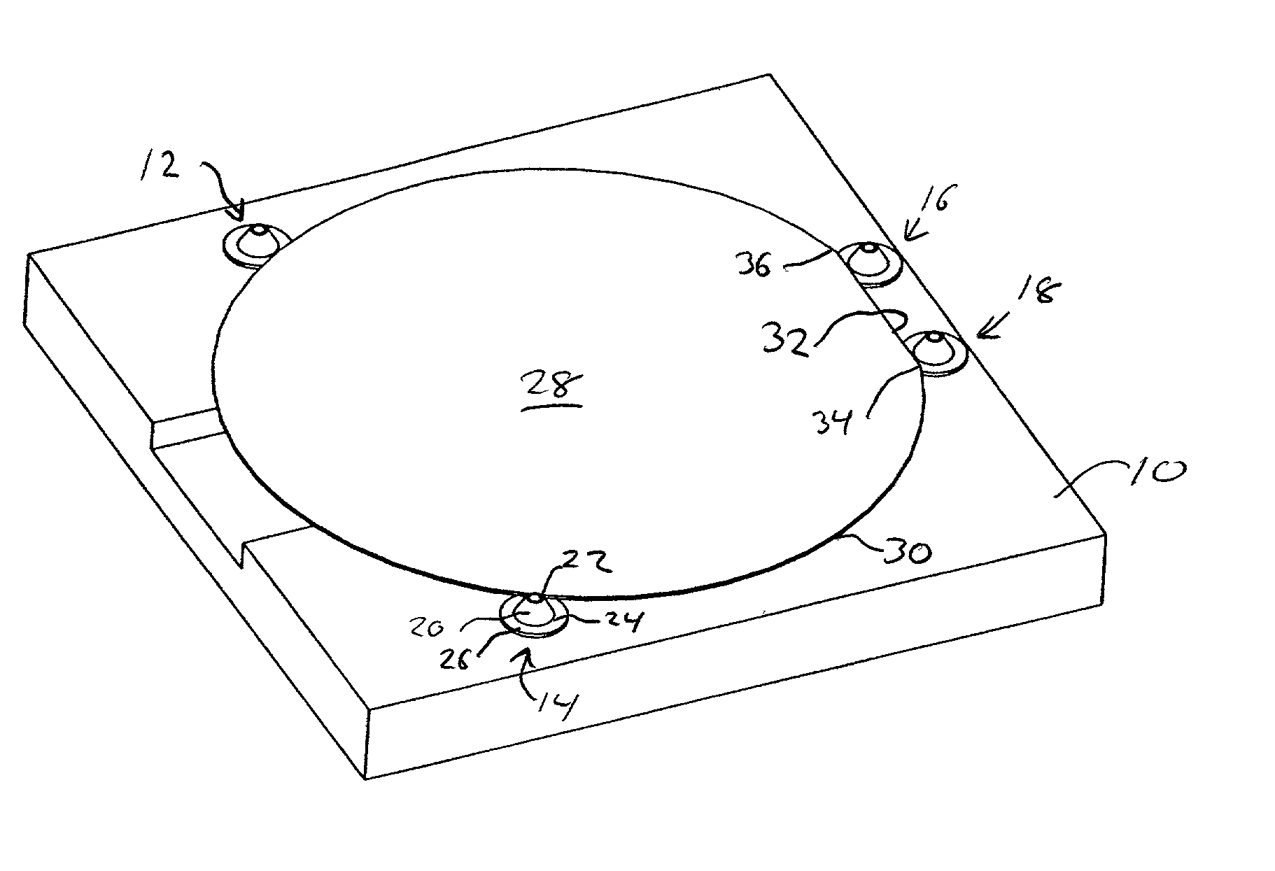
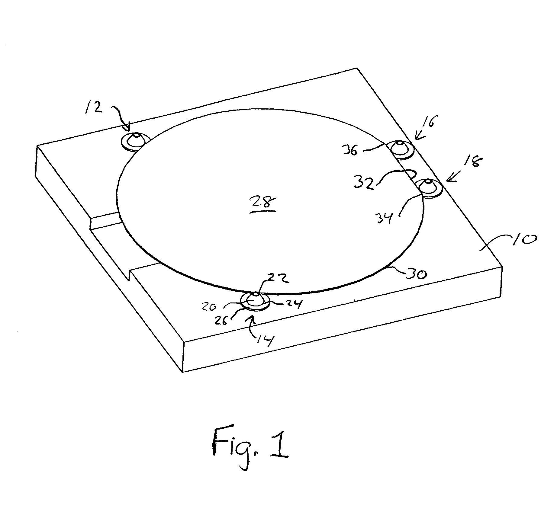
[0023] Referring to FIG. 1, the present invention includes a horizontal base 10 and four conically shaped rollers 12, 14, 16 and 18. Each roller is substantially identical in shape and spins freely about a vertical axis, perpendicular to the plane of the base 10.

[0024] Each roller includes a conical portion 20 having a top 22 and a bottom 24. The bottom of the conical portion defines a circular perimeter and outside that perimeter is an outwardly extending bottom lip 26. The bottom lip has a larger diameter than the diameter of the bottom 24 of the cone 20 such that the lip extends underneath the flatted object 28 and supports it when the flatted object is in the desired orientation, as shown in FIG. 1.

[0025] The flatted object 28, which may be a wafer or a PEC cover, includes a substantially circular perimeter 30 and a flatted chord portion 32. The flatted chord defines a unique rotational orientation for the object 28.

[0026] Although the bottom lip 26 may extend horizontally outw...


PUM


Abstract

A device for aligning a flatted object to a desired orientation. The flatted object has a substantially circular perimeter and a flatted chord portion and may be a silicon wafer or a cover for an electrostatic chuck. The device includes multiple conically shaped rollers that center and rotationally align the object, each roller having a bottom lip for supporting the object. Centering rollers are mounted so that they contact the circular perimeter of the object when it is in the desired orientation. Rotational alignment rollers are mounted so that they contact the flatted chord portion of the object when it is in the desired orientation. When placed on the alignment device, the flatted object passively moves to the desired orientation under the force of gravity.

Description

[0001] 1. Field of the Invention[0002] The present invention relates to devices for centering and rotationally aligning a flatted object to a desired orientation.[0003] 2. Description of Related Art[0004] Microelectronic devices are typically constructed on a wafer having a substantially circular perimeter. During each processing step, the wafer must be correctly aligned by centering the wafer and turning it to the desired rotational orientation. This allows each processing step to proceed in alignment with the work done on the wafer during previous processing steps. The centering is done with respect to the circular perimeter of the wafer, however, in order to detect the correct rotational orientation, the circular perimeter of the wafer must be marked.[0005] One method of marking the circular perimeter of the wafer is with a flatted chord portion. The flatted chord defines a unique rotational orientation for each wafer that is used to consistently align the wafer each time it is m...

Claims


Application Information

Patent Timeline
Patent Type & Authority Applications(United States)
IPC IPC(8): H01L21/68
CPCY10S414/136H01L21/68
Inventor BLANK, RICHARD M.BURKHART, CHRISTOPHER W.
Owner NOVELLUS SYSTEMS
Why Eureka
Try Eureka