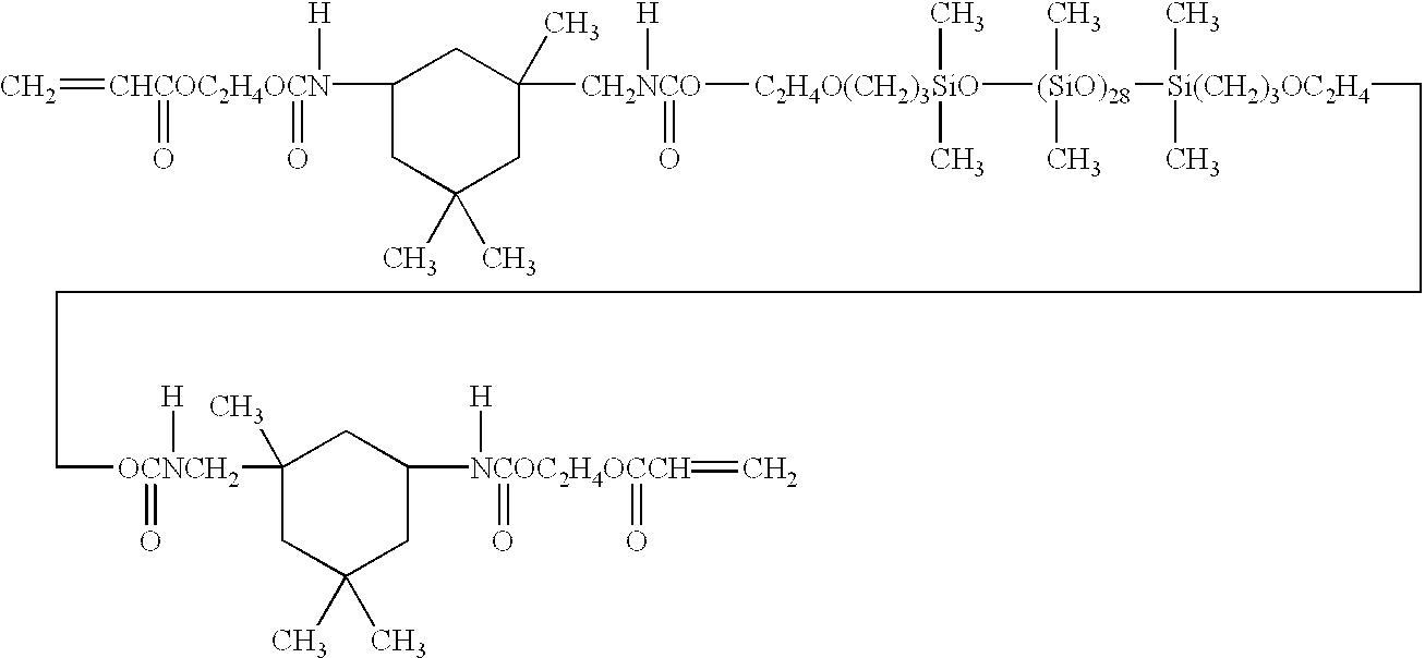
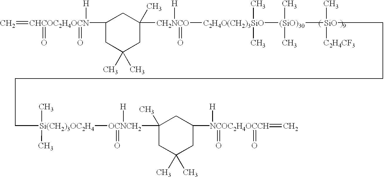
Material for ocular lens
a technology for ocular lenses and materials, applied in the field of ocular lens materials, can solve the problems of difficult material preparation, poor subjective lens comfort, and high sticking property of the surface, and achieve the effects of shortening the polymerization time, reducing residual monomers, and reducing stickiness
- Summary
- Abstract
- Description
- Claims
- Application Information
AI Technical Summary
Benefits of technology
Problems solved by technology
Method used
Image
Examples
examples 9 and 10
[0154] Each ocular lens component obtained by mixing a monomer mixture and a polymerization initiator shown in Table 1 was injected into a mold having shape of a contact lens (made of polypropylene, corresponding to a contact lens having a diameter of about 13 mm and a thickness of 0.1 mm) or a mold having shape of a film (made of polypropylene, corresponding to a film having a diameter of about 15 mm and a thickness of 0.2 mm).
[0155] Next, thermal polymerization was carried out by heating the mold in a drying oven set to 100.degree. C. for 40 minutes to give a copolymer.
[0156] The obtained copolymer was removed from the mold and equilibrated in phosphate-buffered physiological Saline Solution to obtain an ocular lens material.
examples 11 to 13
COMPARATIVE EXAMPLE 9
[0157] Each ocular lens component obtained by mixing a monomer mixture and a polymerization initiator shown in Table 3 was injected into a mold having shape of a contact lens (made of polypropylene, corresponding to a contact lens having a diameter of about 13 mm and a thickness of 0.1 mm) or a mold having shape of a film (made of polypropylene, corresponding to a film having a diameter of about 15 mm and a thickness of 0.2 mm).
[0158] Next, photo polymerization was carried out by irradiating the mold, the irradiance on a wavelength of 365 nm is 2 mW / cm.sup.2 for 60 minutes by using a black light to give a copolymer.
[0159] The obtained copolymer was removed from the mold and equilibrated in phosphate-buffered physiological Saline Solution to obtain an ocular lens material.
examples 14 and 15
[0209] Each ocular lens component obtained by mixing a monomer mixture and a polymerization initiator shown in Table 7 was injected into a mold having shape of a button (made of polypropylene, corresponding to a button having a diameter of about 12 mm and a thickness of about 5 mm).
[0210] Next, photo polymerization was carried out by irradiating the mold with ultraviolet ray having a wavelength of 365 nm in illuminance of 2 mW / cm.sup.2 for 60 minutes by using a black light to give a copolymer. The obtained copolymer was removed from the mold.
PUM
| Property | Measurement | Unit |
|---|---|---|
| Fraction | aaaaa | aaaaa |
| Percent by mass | aaaaa | aaaaa |
| Angle | aaaaa | aaaaa |
Abstract
Description
Claims
Application Information
 - R&D
- Intellectual Property
- Life Sciences
- Materials
- Tech Scout
- Unparalleled Data Quality
- Higher Quality Content
- 60% Fewer Hallucinations
Browse by: Latest US Patents, China's latest patents, Technical Efficacy Thesaurus, Application Domain, Technology Topic, Popular Technical Reports.
© 2025 PatSnap. All rights reserved.Legal|Privacy policy|Modern Slavery Act Transparency Statement|Sitemap|About US| Contact US: help@patsnap.com


