System to remotely control and monitor devices and data

a technology for monitoring devices and data, applied in the field of remote control, can solve the problems of complex rtus, large man-hours and travel time, and difficult operation of remote control devices,

Inactive Publication Date: 2002-12-26
WATKINS GREGG S
View PDF3 Cites 42 Cited by
  • Summary
  • Abstract
  • Description
  • Claims
  • Application Information

AI Technical Summary

Problems solved by technology

Generally, the process of remotely controlling and monitoring devices and data has been a manual and non-remote task requiring lots of man hours and travel time.
The RTUs are generally very complex to use.
These devices are not very user friendly and usually require an engineering type of person to use and operate them.
The problem with telephone lines and private wireless networks are that they are often very expensive to both install and operate due to trenching at remote locations, long wire runs, monthly operation fees, tower installation, maintenance, etc.
The problem with this system and method is that many users often prefer to be able to control their devices and data from their own PC without having to rely on a remotely located Host-type system that many users access.
If there is telephone access to the system and/or devices and data, this access is generally limited and provides override functionality only.
However, these systems do not allow for the public-accessible long-range wireless remote controlling and monitoring of devices and data; including the ability to be operated (monitored, programmed and control

Method used


Image

  • System to remotely control and monitor devices and data
  • System to remotely control and monitor devices and data
  • System to remotely control and monitor devices and data

Examples


Embodiment Construction

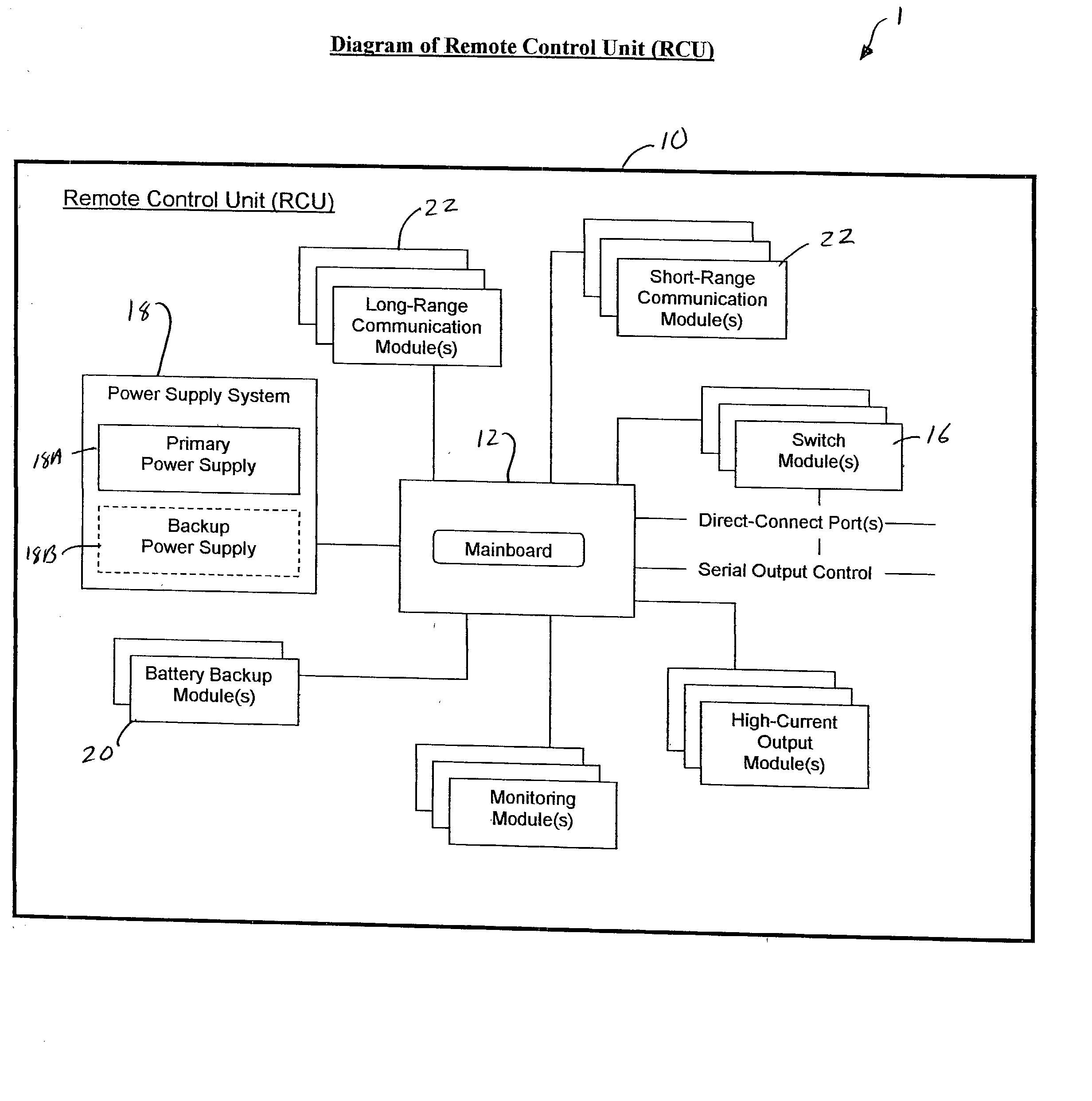
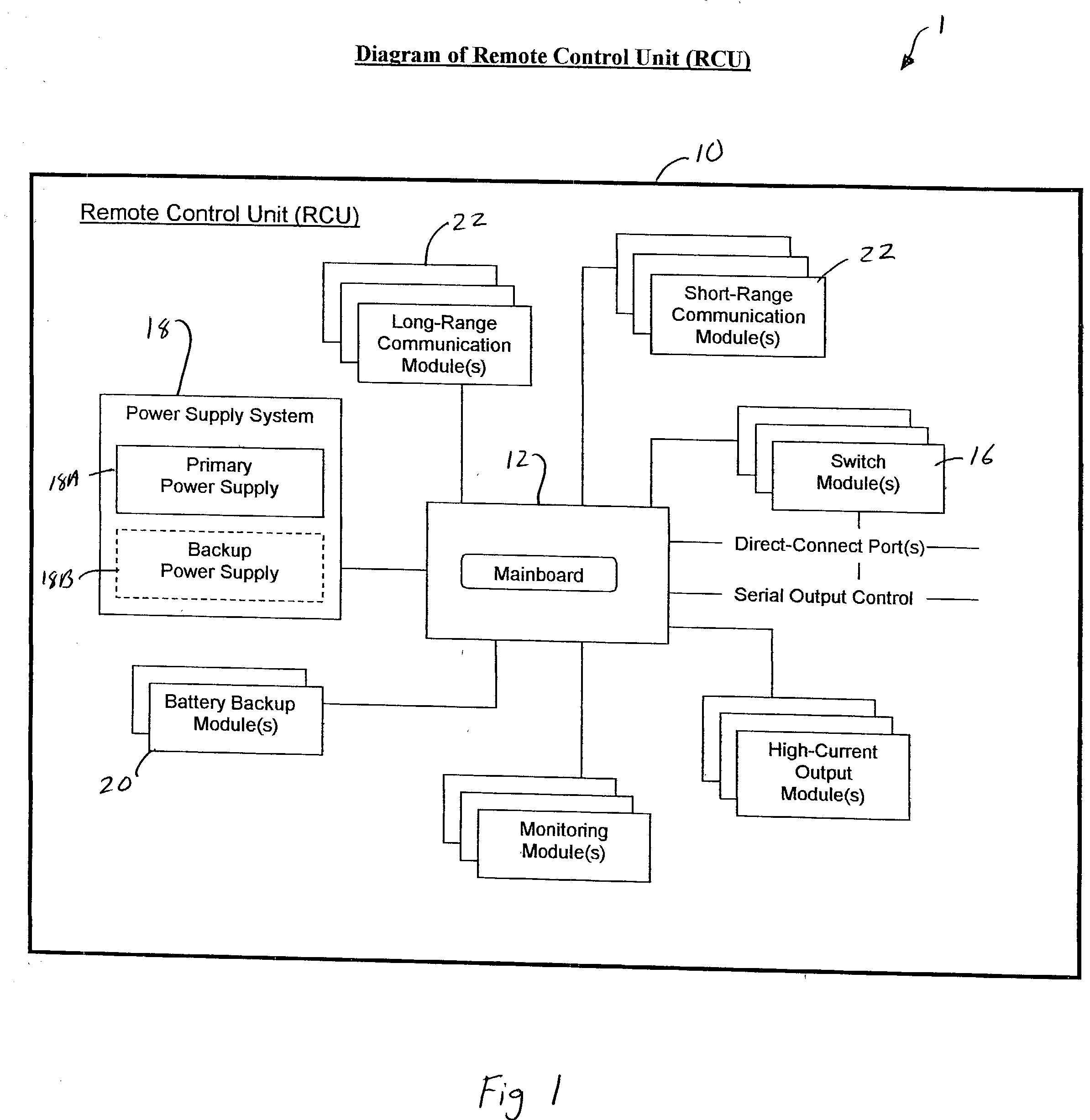
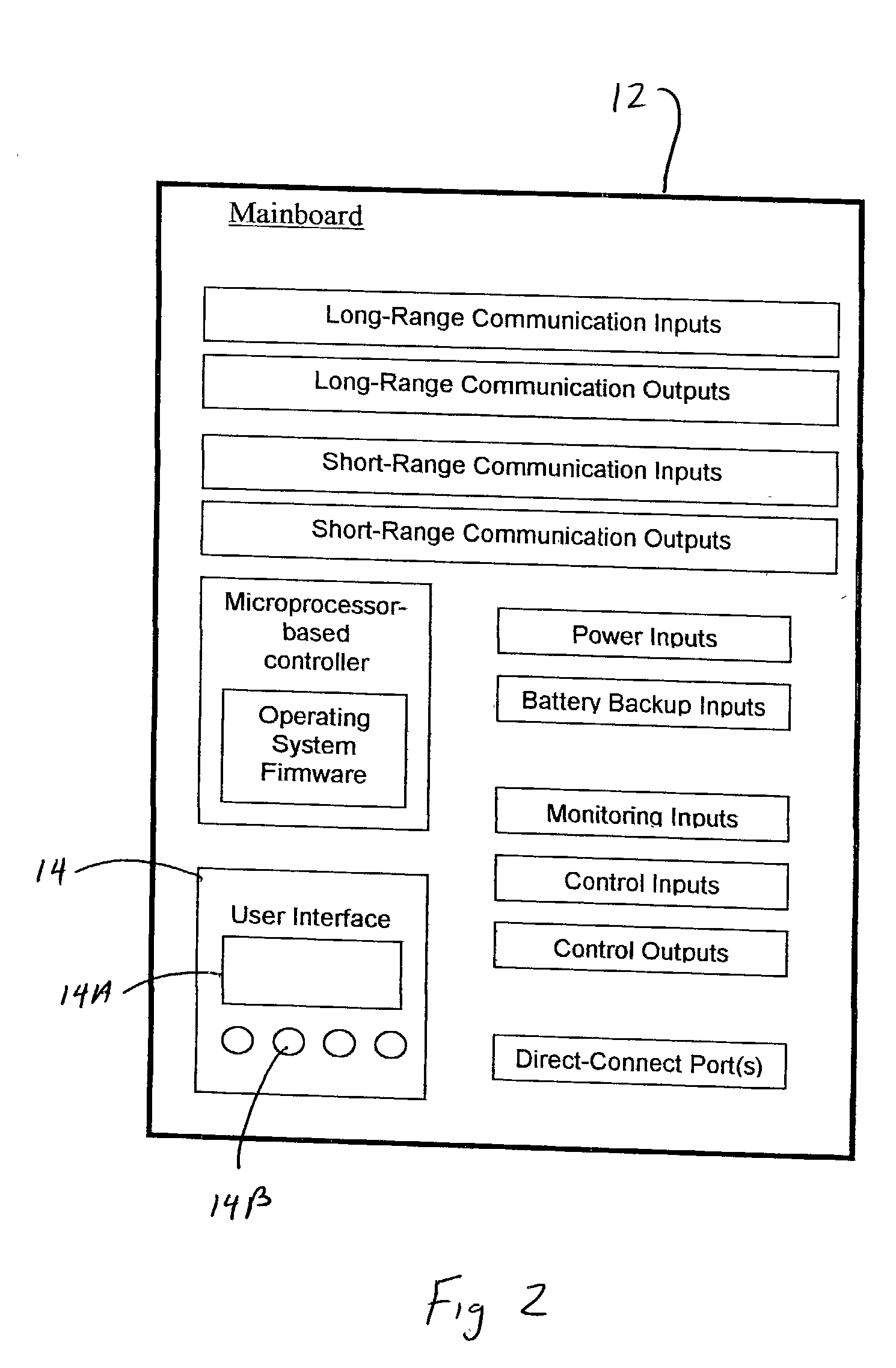
[0021] In accordance with one embodiment of the present invention a system to remotely control and monitor devices and data is disclosed. The system uses a Remote Control Unit having a plurality of modules. A mainboard is the primary intersection point for integrating all the modules. The modules may be integrated with the mainboard on a `plug-in` basis, hard-wired or wirelessly connected. A Power Supply System to provide power to the Remote Control Unit. One or more Communication Modules is used to transfer data to and from the Remote Control Unit. An Output Control Module is provided which receive signals from the mainboard to control operation of the devices. An Input Control Module is used to receive operation commands from push buttons or switches of the system. A Monitoring Input Module is provided which allows for the monitoring of both analog and digital data. An Operating System (OS) is programmed in the RCU. The OS manages the data received from monitored inputs, communica...


PUM


Abstract

A system to remotely control and monitor devices and data uses a Remote Control Unit having a plurality of modules. A mainboard is the primary intersection point for integrating all the modules. A Power Supply System to provide power to the Remote Control Unit. One or more Communication Modules is used to transfer data to and from the Remote Control Unit. An Output Control Module is provided which receive signals from the mainboard to control operation of the devices. An Input Control Module is used to receive operation commands from push buttons or switches of the system. A Monitoring Input Module is provided which allows for the monitoring of both analog and digital data. An Operating System is programmed in the RCU. The OS manages the data received from monitored inputs, communication modules, other input modules, and local user interface, prepares and uploads data to the communications modules required to be sent out, performs various on and off functions of the outputs at required times, runs internal calculations for sunrise and sunset, date and time upkeep, and operates a display of a local user interface. A Remote User Interface (RUI) is used to send and receive commands and information to or from the system wherein information, data and commands may come directly from or to the RCUs, and a PC with Control and Monitoring Software (CMS) connected to the system.

Description

[0001] This patent application is claiming the benefit of the U.S. Provisional Application having an application number of 60 / 300,283, filed Jun. 22, 2001, in the name of Gregg S. Watkins, and entitled "SYSTEM TO REMOTELY CONTROL AND MONITOR DEVICES".[0002] 1. Field of the Invention[0003] This invention relates to remote controls and, more specifically, to a system for remotely controlling devices and / or remotely monitoring devices and processes and / or remotely collecting data, and a related method to operate such a system. The control, monitoring, and / or collection of data can be applied to virtually anything such as devices, assets, digital data, analog data, processes, instrumentation, weather and environmental conditions, etc.[0004] 2. Description of the Prior Art[0005] Generally, the process of remotely controlling and monitoring devices and data has been a manual and non-remote task requiring lots of man hours and travel time. For example, for controlling the operation and mai...

Claims


Application Information

Patent Timeline
IPC IPC(8): H04L12/26
CPCH04L12/2602H04L43/14H04L43/00
Inventor WATKINS, GREGG S.
Owner WATKINS GREGG S
Why Eureka
Try Eureka