Laser beam machining apparatus and laser beam machining method

a laser beam and machining technology, applied in the direction of manufacturing tools, vehicular safety arrangements, pedestrian/occupant safety arrangements, etc., can solve the problems of spoiling the external appearance, limiting driving activity, and difficulty in drilling blind holes in the instrument panel

Inactive Publication Date: 2003-01-02
KOMATSU IND CORP
View PDF1 Cites 87 Cited by
  • Summary
  • Abstract
  • Description
  • Claims
  • Application Information

AI Technical Summary

Problems solved by technology

With the above structure of covering the air bag, however, the problem of spoiling the external appearance arises as the outward form of the cover plate or the groove of the opening portion is exposed on the front surface of the instrument panel.
A further problem is that the reflection of the outward form of the cover plate or the grooves of the opening portion on the front window also puts a restraint on driving activity.
Nevertheless, because instrument panels are curved and of uneven thickness when they are produced by molding, it has been difficult to drill blind holes in the instrument panel so that the remain thickness is secured uniformly.
Therefore, a sensor for detecting the laser beam or the detection beam is needed to be provided on a supporting member such as a jig for supporting a workpiece to be subjected to machining and in a position corresponding to a laser nozzle in such a manner that the sensor is movable integrally with the workpiece on the opposite side of the workpiece, and this makes the detection device not only complicated in construction but also expensive.
The problem in this case is that the necessity of adjusting the detection level before the workpiece is subjected to machining makes it troublesome to detect slight variation in the thickness of the workpiece.
According to the first prior art, moreover, there is the possibility that as the laser beam is ...

Method used


Image

  • Laser beam machining apparatus and laser beam machining method
  • Laser beam machining apparatus and laser beam machining method
  • Laser beam machining apparatus and laser beam machining method

Examples


first embodiment

[0094] The following modification can be made to the invention.

[0095] According to the first embodiment of the invention, the number of output pulses P1 or P2 as the irradiation output power of the laser beam controlled by the control unit 16 is set changeable. On the other hand, the output power or output frequency of a laser beam as the irradiation output power of the laser beam is set changeable instead of the number of output pulses.

[0096] According to the first embodiment of the invention, moreover, the workpiece 12 subjected to the laser beam machining is an instrument panel for covering the air bag of an automobile. On the other hand, the invention is applied to forming grooves in a panel for covering an air bag to be incorporated in a steering wheel or any industrial material other than an instrument panel free from machining scars left in its surface.

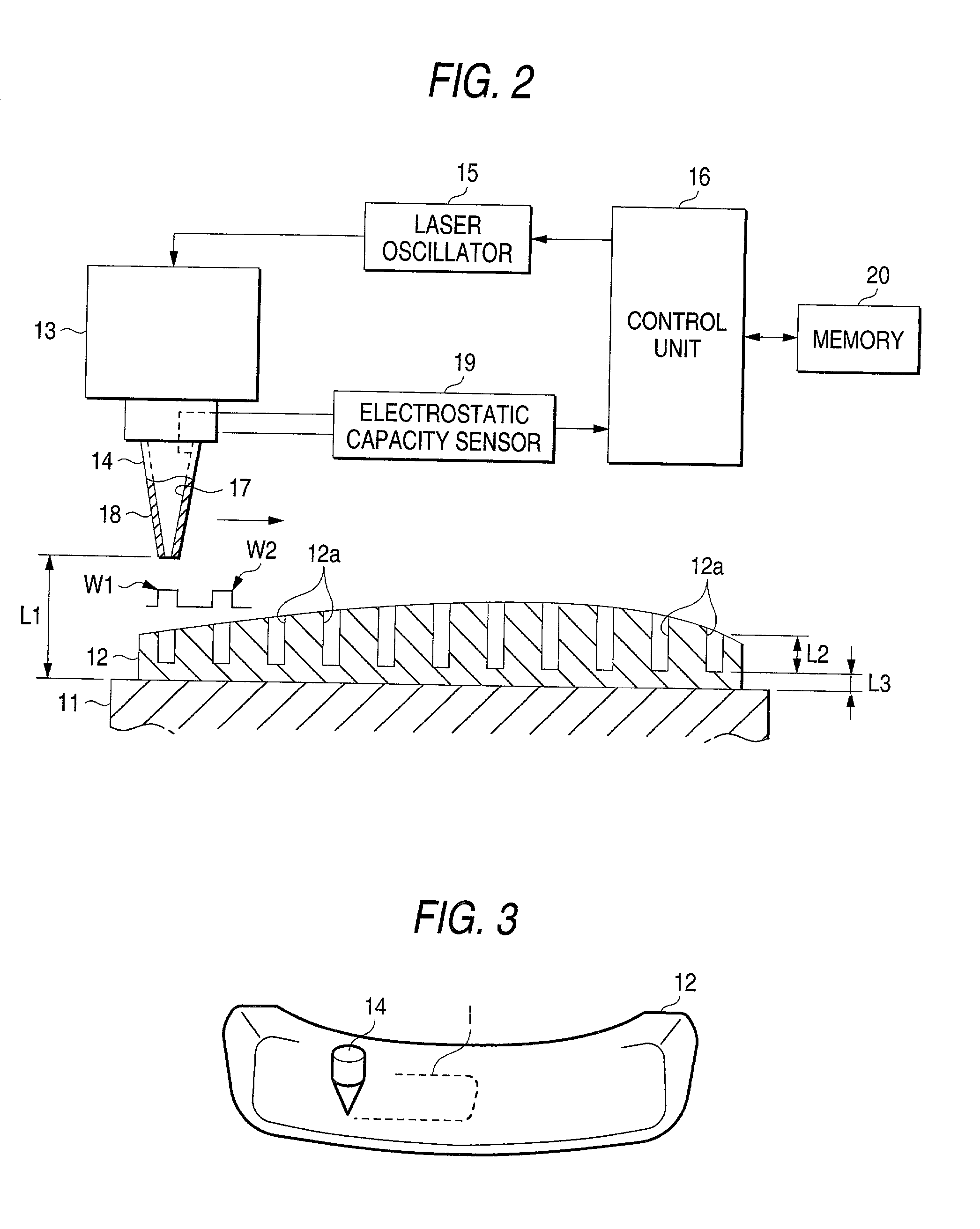
[0097] According to the first embodiment of the invention, machining position data on the plurality of blind holes 12a, relat...

second embodiment

[0101] the invention will now be described with reference to the drawings.

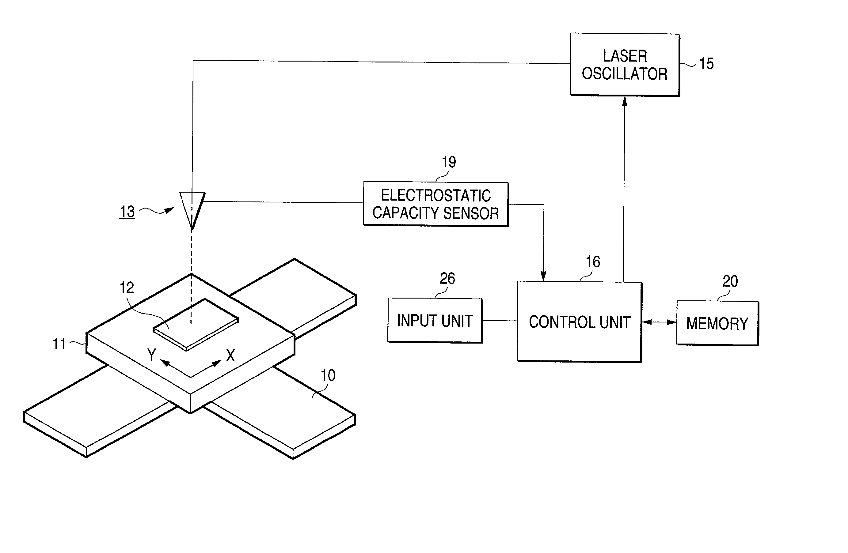
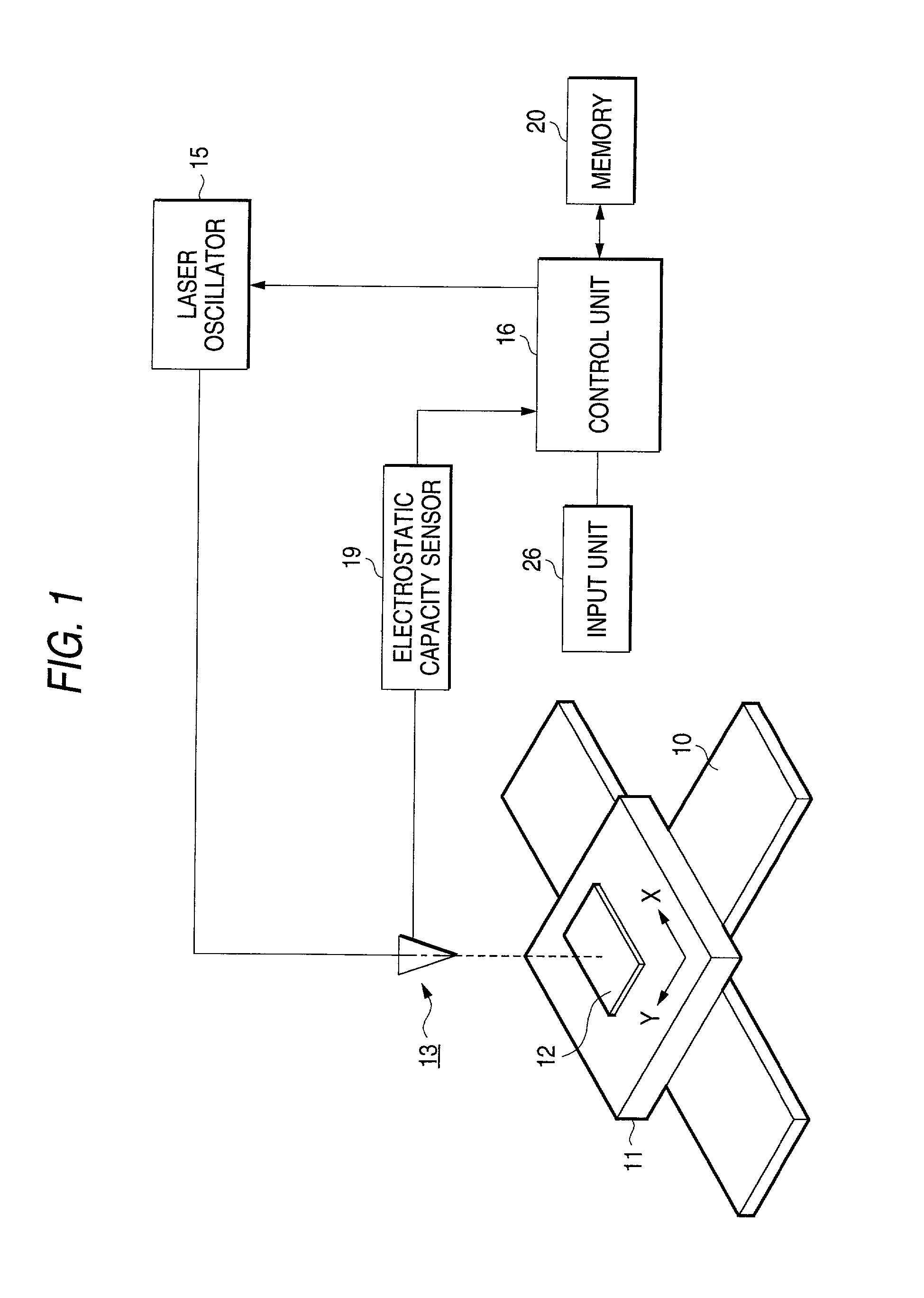
[0102] FIG. 7 shows a laser beam machining apparatus according to the second embodiment. Since respective constructions of a support member 11 forming a jig and a laser head 13 are substantially identical with those of the first embodiment, these detailed descriptions are omitted in this embodiment. Further, a workpiece 12 to be machined is an instrument panel shown in FIGS. 2 and 3 as well as the first embodiment.

[0103] As shown in FIG. 7, a laser oscillator 15 is connected to the laser head 13. A plurality of mirrors 21 to 23 and a focusing lens 14a are disposed between the laser oscillator 15 and the laser nozzle 14, so that a laser beam path is formed between the laser head 13 and the laser oscillator 15. One of the mirrors 21 to 23 is used as a half mirror 21 and part of the laser beam is passed through the half mirror. A detection sensor 24 as a laser beam detection unit is disposed on an optical transmi...


PUM

PropertyMeasurementUnit
Fractionaaaaaaaaaa
Fractionaaaaaaaaaa
Thicknessaaaaaaaaaa

Abstract

A laser beam machining apparatus forms blind holes at predetermined intervals in a workpiece by intermittently irradiating a laser beam from a laser nozzle to the workpiece while the laser nozzle and the workpiece being moved relatively. During the time the workpiece is subjected to machining, the electrostatic capacity between the support member and the laser nozzle is detected by an electrostatic capacity sensor while the workpiece made of conductive material is supported on the support member. The irradiation output power is controlled by a control unit which operates to vary the number of output pulses from the laser nozzle each time one hole is formed according to the result detected in response to variation in the thickness of the workpiece.

Description

[0001] 1. Field of the Invention[0002] The present invention relates to a laser beam machining apparatus for forming a tearable portion in a workpiece such as automotive instrument panel by irradiating a laser beam and a laser beam machining method therefor.[0003] 2. Description of the Related Art[0004] Air bags for passenger seats of automobiles are generally placed on the inside of instrument panels. Moreover, an opening is formed in the instrument panel in a position opposite to the air bag and a cover plate is mounted over the opening; or otherwise there is formed a groove for use in cleaving a predetermined opening portion in the instrument panel though no opening is provided therein. In this case, the air bag is normally covered with the cover plate or the opening portion and when the air bag is activated, the cover plate is broken or the opening portion is cloven out of the groove so that the air bag is inflated outside the instrument panel.[0005] With the above structure of ...

Claims


Application Information

Patent Timeline
IPC IPC(8): B23K26/04B23K26/38B60R21/2165
CPCB23K26/04B23K26/385B60R21/2165B23K26/389
Inventor KANAYA, SHUSOMORITA, YUICHI
Owner KOMATSU IND CORP
Why Eureka
Try Eureka