Polymer electrolyte fuel cell

a fuel cell and electrolyte technology, applied in the field of polymer electrolyte fuel cells, can solve the problems of remarkably worsening the distribution to the respective separator plates, difficult to check the surface and rear face of the separator plate, and difficult to achieve the adequate ratio of the opening area of each manifold aperture to the total sectional area of each flow channel

Inactive Publication Date: 2003-01-02
PANASONIC CORP
View PDF5 Cites 75 Cited by
  • Summary
  • Abstract
  • Description
  • Claims
  • Application Information

AI Technical Summary

Benefits of technology

0012] An oxidant gas manifold aperture for an inlet is arranged on one short side of the rectangular separator plate, while an oxidant gas manifold aperture for an outlet is arranged on the other short side. A fuel gas manifold aperture for an inlet and a fuel gas manifold aperture for an outlet ar...

Problems solved by technology

It is accordingly difficult to check the surface and the rear face of the separator plate.
The excessively small flow rate has a significant effect on the dynamic pressure and remarkably worsens the distri...

Method used


Image

  • Polymer electrolyte fuel cell
  • Polymer electrolyte fuel cell
  • Polymer electrolyte fuel cell

Examples


embodiment 1

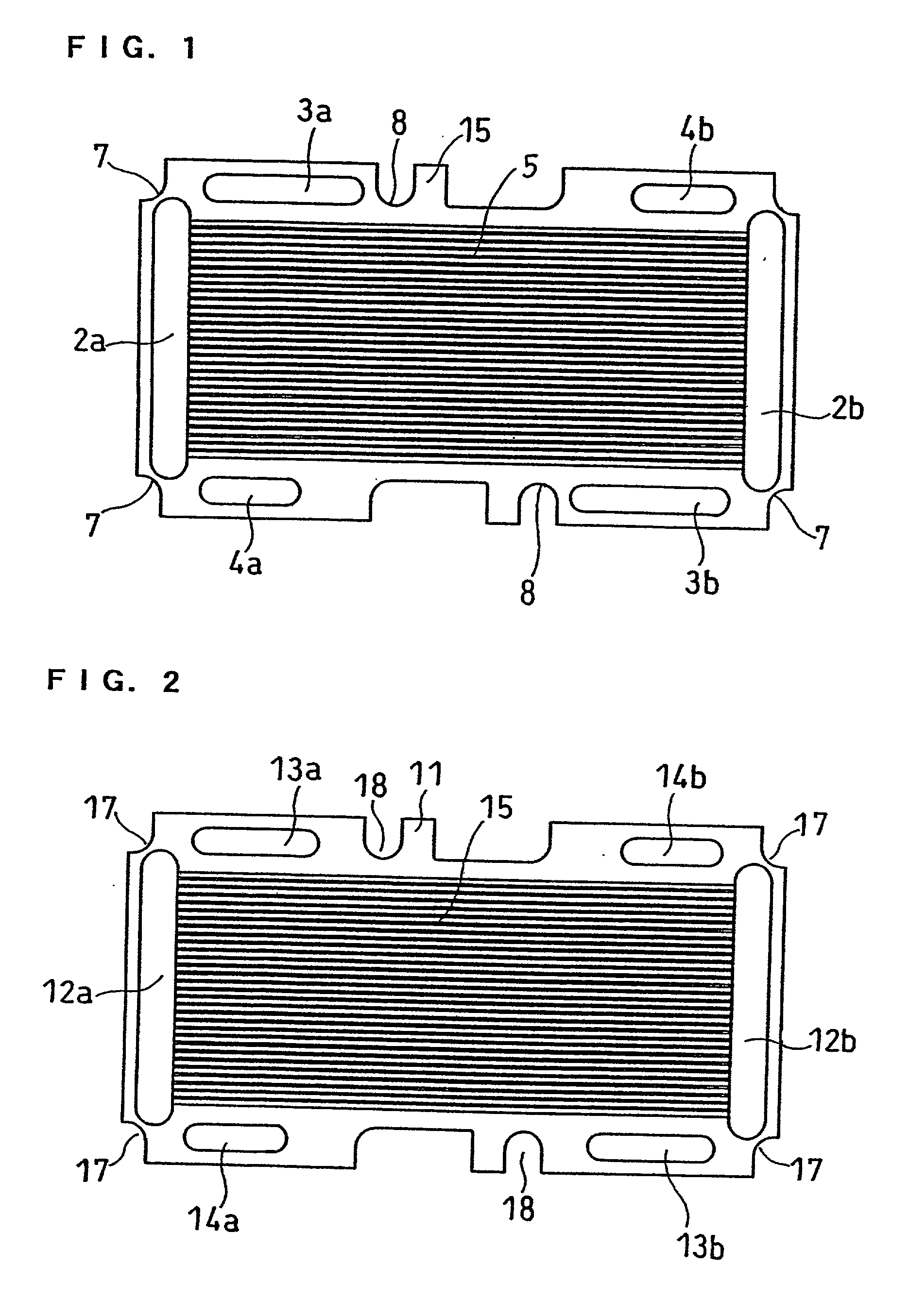
[0075] The structure of a separator plate included in a polymer electrolyte fuel cell of one embodiment is illustrated in FIG. 1. FIG. 1 is a front view showing a separator plate seen from a cathode side.

[0076] This separator plate 1 is, for example, a machined rectangular glassy carbon plate, and has a pair of manifold apertures 2a and 2b for an oxidant gas arranged on short sides thereof, as well as a pair of manifold apertures 3a and 3b for cooling water and a pair of manifold apertures 4a and 4b for a fuel gas arranged on longitudinal sides thereof. The manifold apertures 2a, 3a, 4a are formed at different sides. The manifold apertures 2b, 3b, and 4b are also formed at different sides. The cooling water manifold apertures 3a and 3b are respectively arranged opposite to the fuel gas manifold apertures 4a and 4b. One manifold aperture in each pair is an inlet, and the other is an outlet. For example, the manifold apertures 2a, 3a, and 4b are inlets, whereas the manifold apertures ...

embodiment 2

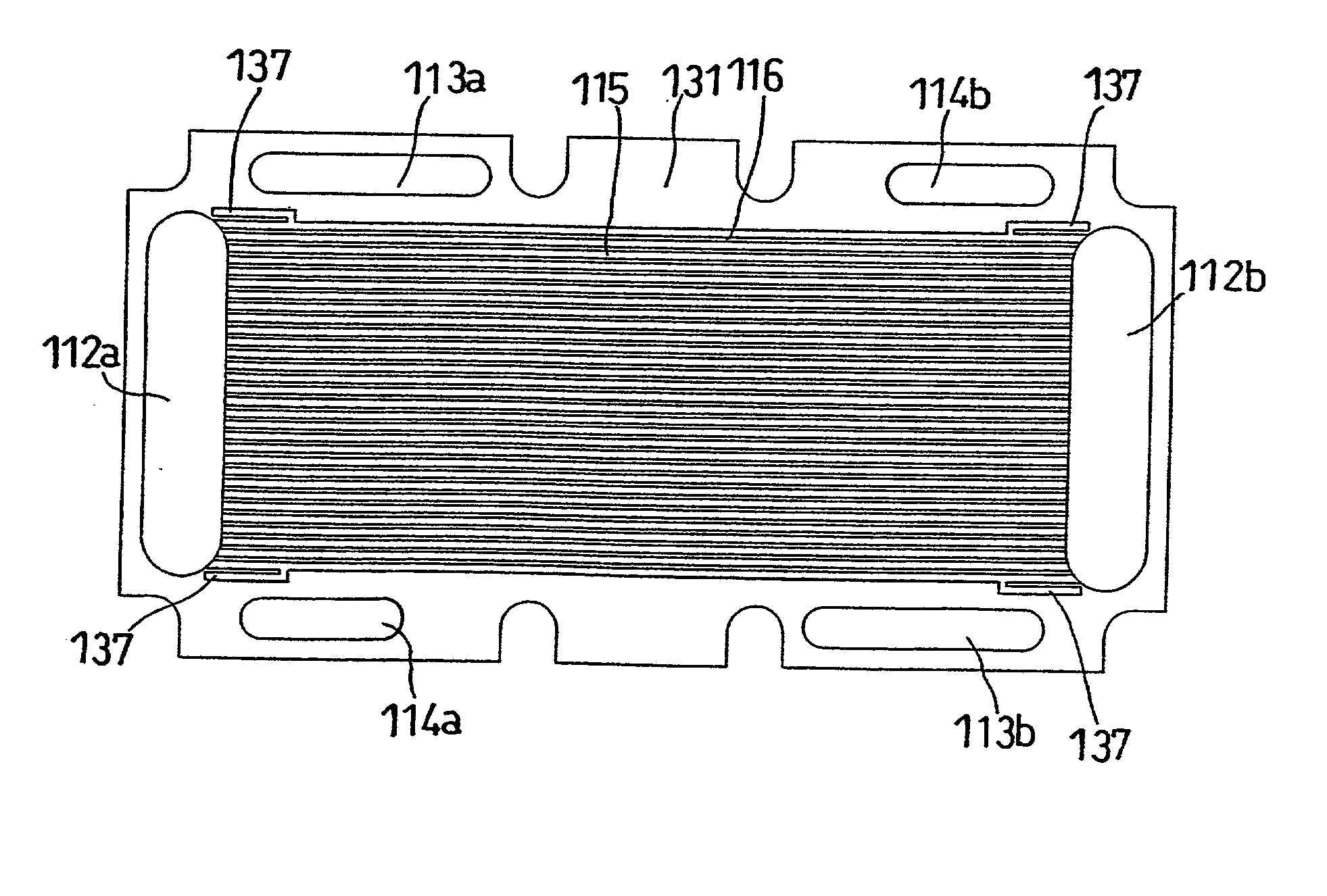
[0081] The structure of a separator plate included in a polymer electrolyte fuel cell of another embodiment is illustrated in FIG. 2.

[0082] FIG. 2 is a front view showing a separator plate seen from the cathode side.

[0083] This separator plate 11 is, for example, a machined rectangular glassy carbon plate, and has a pair of manifold apertures 12a and 12b for the oxidant gas arranged on short sides thereof, as well as a pair of manifold apertures 13a and 13b for cooling water and a pair of manifold apertures 14a and 14b for the fuel gas arranged on longitudinal sides thereof. The manifold apertures 12a , 13a , 14a are formed at different sides. The manifold apertures 12b , 13b , and 14b are also formed at different sides. The cooling water manifold apertures 13a and 13b are respectively arranged opposite to the fuel gas manifold apertures 14a and 14b. Unlike Embodiment 1, the opening areas of the three types of manifold apertures, the oxidant gas manifold aperture, the fuel gas manif...

embodiment 3

[0090] FIG. 4 is a front view illustrating a separator plate in still another embodiment seen from the cathode side.

[0091] This separator plate 31 has a pair of manifold apertures 32a and 32b for the oxidant gas arranged on short sides thereof, as well as a pair of manifold apertures 33a and 33b for cooling water and a pair of manifold apertures 34a and 34b for the fuel gas arranged on longitudinal sides thereof. The manifold apertures 32a, 33a, 34a are formed at different sides. The manifold apertures 32b, 33b, and 34b are also formed at different sides. The cooling water manifold apertures 33a and 33b are respectively arranged opposite to the fuel gas manifold apertures 34a and 34b. Like Embodiment 1, the opening areas of the three types of manifold apertures, the oxidant gas manifold aperture, the cooling water manifold aperture, and the fuel gas manifold aperture, decrease in this order. A plurality of straight grooves are formed as a gas flow channel 35 to connect the oxidant g...


PUM


Abstract

A polymer electrolyte fuel cell of the present invention includes a hydrogen ion-conductive polymer electrolyte membrane, an anode and a cathode sandwiching the hydrogen ion-conductive polymer electrolyte membrane, an anode-side conductive separator plate having a gas flow channel for supplying a fuel gas to the anode, and a cathode-side conductive separator plate having a gas flow channel for supplying an oxidant gas to the cathode. Each of the anode-side conductive separator plate and the cathode-side conductive separator plate is rectangle in shape and has an oxidant gas manifold aperture for an inlet arranged on one short side thereof, an oxidant gas manifold aperture for an outlet arranged on the other short side thereof, a fuel gas manifold aperture for an inlet and a fuel gas manifold aperture for an outlet arranged on different longitudinal sides thereof, and a cooling water manifold aperture for an inlet and a cooling water manifold aperture for an outlet arranged on the different longitudinal sides thereof. The respective fuel gas manifold apertures are disposed opposite to the cooling water manifold apertures. The oxidant gas manifold apertures, the fuel gas manifold apertures, and the cooling water manifold apertures have openings of different shapes.

Description

DESCRIPTIONPOLYMER ELECTROLYTE FUEL CELL[0001] 1. Technical Field[0002] The present invention relates to a polymer electrolyte fuel cell applicable for portable power sources, power sources for electric vehicles, and domestic cogeneration systems.[0003] 2. Background Art[0004] Fuel cells using a polymer electrolyte generate electric power and heat simultaneously by electrochemically reacting a fuel gas containing hydrogen and an oxidant gas containing oxygen, such as air. The fuel cell basically includes a polymer electrolyte membrane that selectively transports hydrogen ions and a pair of electrodes disposed on both faces of the electrolyte membrane. The electrodes comprises a catalyst layer mainly composed of carbon power with a platinum group metal catalyst carried thereon and a gas diffusion layer which has gas permeability and electronic conductivity and is formed on the outer face of the catalyst layer.[0005] In order to prevent leakage of the supplied fuel gas and oxidant gas...

Claims


Application Information

Patent Timeline
IPC IPC(8): H01M4/86H01M4/90H01M8/02H01M8/04H01M8/10
CPCH01M4/9083H01M8/0204H01M8/0206H01M8/0213H01M8/0228H01M8/0247H01M8/0254H01M8/0256H01M8/0263H01M8/0267H01M8/0269H01M8/04029H01M8/04552H01M2300/0082Y02E60/50H01M8/242H01M8/2457H01M8/2483H01M8/02H01M8/0273
Inventor OHARA, HIDEOKUSAKABE, HIROKIYAMAZAKI, TATSUTOSUGOU, MASAYOHASE, NOBUHIROTAKEGUCHI, SHINSUKEYAMAMOTO, YOSHIAKIMATSUMOTO, TOSHIHIROFUJII, SATORUHATOH, KAZUHITOHOSAKA, MASATONIIKURA, JUNJINISHIDA, KAZUFUMIKANBARA, TERUHISA
Owner PANASONIC CORP
Why Eureka
Try Eureka