
Method and apparatus for increasing flow capacity associated with a valve

a technology of flow capacity and valve, applied in the direction of valve arrangement, basic electric elements, electrical equipment, etc., can solve the problems of precision instrument performance and improper product formation of products formed using precision instruments

Inactive Publication Date: 2003-01-09
NIKON CORP
View PDF2 Cites 12 Cited by
  • Summary
  • Abstract
  • Description
  • Claims
  • Application Information

AI Technical Summary

Problems solved by technology

When the performance of a precision instrument is adversely affected, as for example by vibrations, products formed using the precision instrument may be improperly formed and, hence, defective.
For instance, a photolithography machine which is subjected to vibratory motion may cause an image projected by the photolithography machine to move, and, as a result, be aligned incorrectly on a projection surface such as a semiconductor wafer.

Method used


Image

  • Method and apparatus for increasing flow capacity associated with a valve
  • Method and apparatus for increasing flow capacity associated with a valve
  • Method and apparatus for increasing flow capacity associated with a valve

Examples


Embodiment Construction

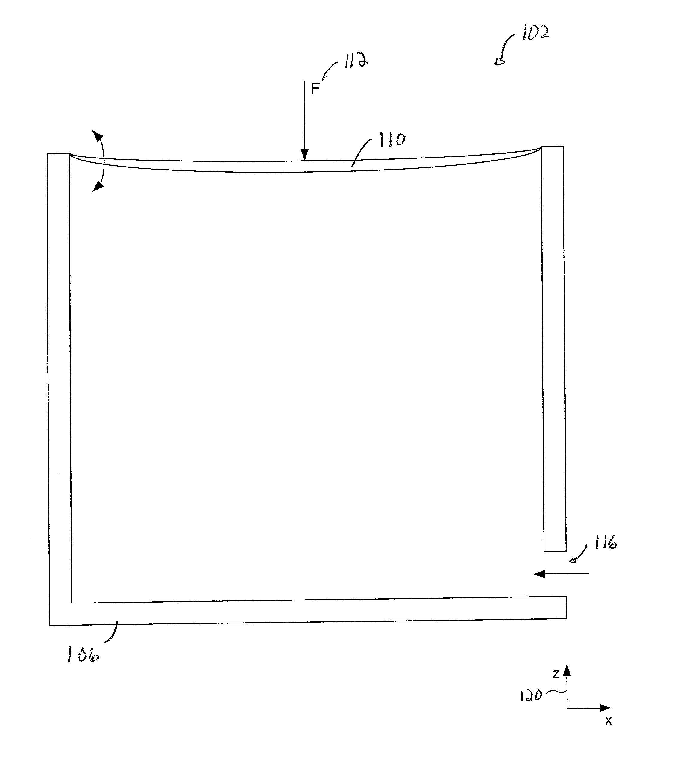
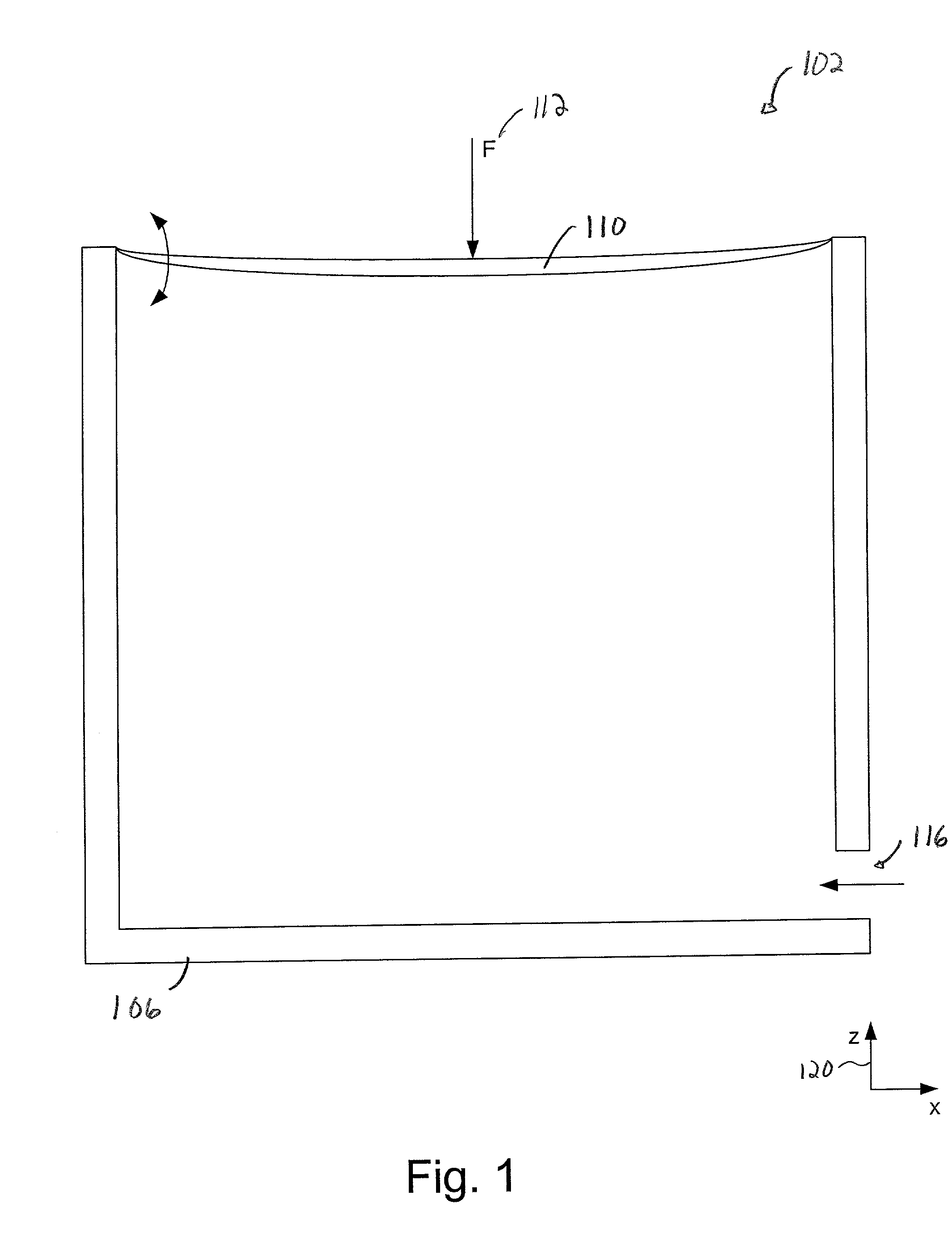
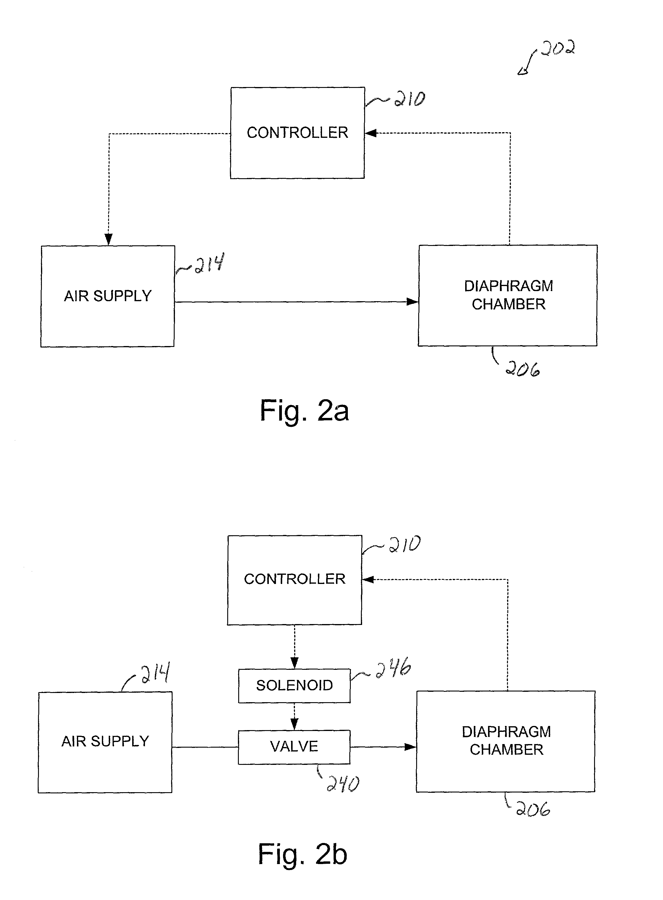
[0031] In order to effectively increase the flow capacity associated with a controlled valve, the limited pressure capacity or the limited flow capacity of the valve may be augmented by providing an alternate flow path to the flow path associated with the valve. Implementing a bypass or a shunt with respect to a valve enables the flow of air through the valve to be augmented by the flow of air through the bypass. As such, the flow rate or the flow capacity associated with the valve is effectively increased, while the flow may be fine tuned, or adjusted, relatively quickly through the use of the controlled valve. That is, the bulk of air flow provided to a chamber may be provided through the bypass, while a substantially smaller, readily controllable amount may be provided to the chamber through the valve. Hence, the use of a bypass allows for a faster response to a change in the pressure level in the chamber by enabling changes to the pressure level to be accommodated by the valve, ...


PUM


Abstract

Methods and apparatus for efficiently compensating for pressure changes in a active vibration isolation system are disclosed. According to one aspect of the present system, system that reduces the vibrations experienced by a mass includes a chamber that supports the mass, a control device, a valve mechanism, and a bypass mechanism. The control device monitors a pressure level within the chamber. The valve mechanism includes a first flow path that is in fluid communication with the chamber. The valve mechanism also alters a capacity of the first flow path in response to a control signal generated by the controller. Finally, the bypass mechanism defines a second flow path that enables fluid to flows through the second flow path into the chamber. The second flow path is parallel to the first flow path to enable parallel fluid flow to occur.

Description

[0001] 1. Field of Invention[0002] The present invention relates generally to controlling vibrations in mechanical systems using controlled valve mechanisms. More particularly, the present invention relates to a valve bypass arrangement which effectively increases the flow capacity associated with a controlled valve in a vibration control system to enable vibrations to be efficiently controlled and dampened.[0003] 2. Description of the Related Art[0004] For precision instruments such as photolithography machines which are used in semiconductor processing, factors which affect the performance, e.g., accuracy, of the precisions instruments generally must be dealt with and, insofar as possible, eliminated. When the performance of a precision instrument is adversely affected, as for example by vibrations, products formed using the precision instrument may be improperly formed and, hence, defective. For instance, a photolithography machine which is subjected to vibratory motion may cause...

Claims


Application Information

Patent Timeline
IPC IPC(8): F16K37/00
CPCF16K37/00
Inventor YUAN, BAU-SANLEE, MARTIN E.REYNOLDS, ED. E.
Owner NIKON CORP
Learn More