
Display device, drive circuit thereof, driving method therefor, and electronic equipment

Inactive Publication Date: 2003-01-16
SEIKO EPSON CORP
View PDF4 Cites 24 Cited by
  • Summary
  • Abstract
  • Description
  • Claims
  • Application Information

AI Technical Summary

Benefits of technology

[0013] According to this construction, even when an ON pixel and an OFF pixel alternately appear in a data line, there will be a smaller difference between the effective value of a voltage applied to the data line and the effective value of a voltage applied to other data lines, making it possible to restrain the degradation in display quality.
[0032] Electronic equipment according to the present invention is equipped with the aforesaid display device, thus permitting reduced power consumption or the like to be achieved, while restraining the degradation in display quality. Such electronic equipment includes a personal computer, a cellular telephone, and a digital still camera.

Problems solved by technology

Meanwhile, in a display device in which pixels are switched by the two-terminal type switching elements, various modes that lead to degraded display quality exist.
However, performing the intermediate gray scale display in the above four-value driving method inevitably leads to a higher voltage switching frequency of data lines, thus posing a shortcoming in that electric power is wasted due to capacitance accompanying the data lines.
On the other hand, if the four-value driving method (1 / 2H selection, 1H inversion) is not used, then a problem occurs in which display quality is deteriorated, depending upon a mode.
According to this construction, the boundary portion of blocks moves with the elapse of time, so that even if a display difference takes place in the portion, the display difference will not stand out, thus making it difficult to visually recognized it as the degradation in display quality.
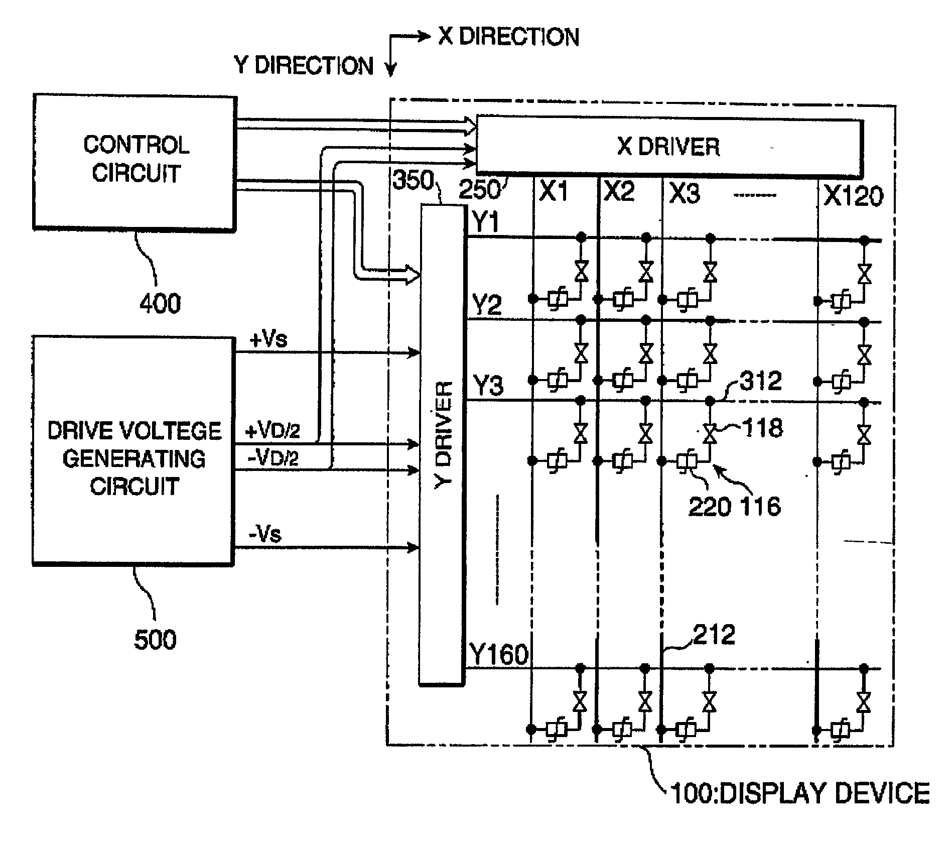
The non-selection voltage and the data voltage may be different rather than the same; however, if they are different, then the number of voltages to be generated by the drive voltage generating circuit 500 increases, resulting in a more complicated configuration accordingly.
Incidentally, the four-value driving method (1H selection, 1H inversion) has been known to pose a problem in that cross talk occurs when the zebra display is performed in which white lines and black lines are alternately displayed in a region A of a display screen 100a, while the rest of the area is set, for example, for white display only as shown in, for example, FIG. 16.
In other words, the problem arises in which white display accompanying shade differences appears in a direction Y with respect to region A.
However, the driving method known as the four-value driving method (1 / 2H selection, 1H inversion) poses a problem in that, especially when gray scale display is carried out, the voltage of the data signal Xj is switched more frequently.
Accordingly, more frequent voltage switching of the data signal Xj means more frequent charging and discharging in the capacitor C.sub.pix and various parasitic capacitors, causing electric power to be consumed.
This is a major factor interfering with the achievement of reduced power consumption.
However, implementing the configuration for correcting selection voltages themselves would involve an increased number of the voltages to be generated by the drive voltage generating circuit 500 (refer to FIG. 1), leading to a complicated configuration.
Furthermore, there are some cases where it is difficult to completely eliminate irregularities even when the configuration for making corrections at block boundaries is used.
Hence, if each frame has a different block boundary, then it becomes difficult to visually recognize irregularities even if the irregularities take place.
Therefore, on a basis of a few frames, irregularities look averaged to naked eye, making it difficult to visually recognize them as irregularities.
There is, however, a possibility of the occurrence of cross talk attributable to the writing not being executed.

Method used


Image

  • Display device, drive circuit thereof, driving method therefor, and electronic equipment
  • Display device, drive circuit thereof, driving method therefor, and electronic equipment
  • Display device, drive circuit thereof, driving method therefor, and electronic equipment

Examples


Embodiment Construction

>

[0214] In the above embodiment, the descriptions have been given of the case where the 8-gray scale display is performed with the 3-bit gray scale data; the present invention, however, is not limited thereto. Alternatively, binary display based on simple 1-bit gray scale (ON-OFF) data may be used, or 4-gray scale display based on 2-bit gray scale data may be used, or 16, 32, 64, . . . , 2.sup.n gray scale display based on 4-bit, 5-bit, 6-bit, . . . , n-bit gray scale data may be used.

[0215] Moreover, three pixels of R (red), G (green), and B (blue) may constitute one dot to perform color display.

[0216] Furthermore, in the embodiment, the descriptions have been given of the case of the normally white mode in which white display is provided when no voltage is applied to the liquid crystal capacitor. Alternatively, a normally black mode in which black display is provided under the same condition may be used.

[0217] In addition, the embodiment has been the transmissive type; alternative...


PUM


Abstract

To reduce power consumption while restraining the occurrence of cross talk at the same time. A plurality of scanning lines are bundled into a block, and the polarities of the selection voltages of scanning signals Yi, Yi+1, Yi+2, and Yi+3 supplied to the scanning lines that belong to the same block are alternately inverted. Furthermore, the polarity of the selection voltage of the scanning signal Yi+3 supplied to the scanning line selected last in the block is the same as the polarity of the selection voltage of the scanning signal Yi+4 supplied to the scanning line selected first in a block following the aforesaid block.

Description

[0001] 1. Field of Invention[0002] The present invention relates to a display device, a drive circuit thereof, a driving method therefor, and electronic equipment that achieves reduced power consumption while restraining degradation in display quality in, for example, a construction wherein switching of pixels is performed by a thin film diode.[0003] 2. Description of Related Art[0004] In recent years, display units making use of electro-optical changes of liquid crystals are being extensively used with a variety of electronic equipment, televisions, etc., as display devices that replace cathode ray tubes (CRT) by taking advantage of their features, such as thin compact designs and lower power consumption.[0005] The display devices may be roughly divided on the basis of a driving system or the like into an active matrix type in which pixels are driven by switching and a passive matrix type in which pixels are driven without using switching elements. Of these, the former type, namely...

Claims


Application Information

Patent Timeline
IPC IPC(8): G02F1/133G02F1/1343G02F1/1365G09G3/20G09G3/36
CPCG09G3/2014G09G3/3614G09G3/367G09G3/3674G09G3/3685G09G2320/0209
Inventor YAMAZAKI, KATSUNORI
Owner SEIKO EPSON CORP
Learn More