Method and apparatus for registering a known digital object to scanned 3-D model

a technology of known digital objects and 3d models, applied in the field of dental and orthodontics, can solve the problems of not being able to store for future retrieval, presenting certain challenges, and obtaining either incomplete or inaccurate three dimensional surface information

Inactive Publication Date: 2003-01-30
ORAMETRIX
View PDF50 Cites 115 Cited by
  • Summary
  • Abstract
  • Description
  • Claims
  • Application Information

AI Technical Summary

Problems solved by technology

In such a manual process, the actual bracket placement is not generally known and therefore cannot be stored for future retrieval during the treatment planning phase.
Performing certain monitoring scans after treatment has been initiated, however, often presents certain challenges.
There are, however, a number of complications that often arise during a monitoring scan that can often result in obtaining either incomplete or inaccurate three dimensional surface information.
For example, monitoring scans are often result in providing an orthodontist incomplete scan data of the entire dentition.
Because of the incomplete nature of certain monitoring scans, the resulting incomplete scan data makes the analysis of the patient's dentition difficult.
The size of the bracket, and the bracket component parts, also pose problems in obtaining accurate scan data.
Obtaining accurate scan data of these types of sharp edges and lines is often difficult since these geometrical structures cause scattering and poor image acquisition.
The small dimension of the bracket, and therefore the bracket component parts (wings, slot, etc.) makes obtaining accurate bracket scan data even more challenging.
These various bracket edges make it difficult to obtain accurate and complete scan information, thereby making it difficult to obtain accurate and complete scan data and therefore construct a 3-D virtual model of the dentition plus brackets.
Due to the small size of bracket wings, bracket slots and their related geometries, the size of the bracket structure further causes complications due to the resolution of a projected pattern that may be used in various 3D scanning technologies.
For example, where a scanner utilizes a resolution of approximately 0.25 mm, obtaining a complete and accurate scan data from a wing of a bracket will be difficult.
Furthermore, obtaining complete and accurate scan data for the slot 3 will be difficult not only because of the slot width but also because of shadowing issues.
Incomplete and inaccurate scan data makes it difficult to construct an accurate three-dimensional model and thereby determine where the bonded bracket actually resides in three-dimensional space.
And, since it is difficult to determine the exact position in 3-D space of the bracket, there will be further difficulty in determining the exact position of the archwire slot, and therefore the required archwire configuration.
These scanning inefficiencies may be further prevalent where the dentition is scanned in-vivo, that is, where the object being scanned (dental appliance) is covered with light scattering elements such as water, saliva, or other types of moisture.
Another scanning quality issue that may arise during treatment concerns performing a monitoring scan after a patient's teeth have moved, as a result of the treatment or biological process.
Because of certain inherent logistical delays, the monitoring scanning process may take place a certain amount of time after the original scan was completed.
Therefore, the resulting subsequent monitoring scan may confirm that the original virtual 3-D model is no longer correct and must therefore be updated to reflect various new tooth positions.
Another need arises where it is generally not possible to scan an object due to restrictions in certain types of scanning technologies (e.g., scan resolutions).

Method used


Image

  • Method and apparatus for registering a known digital object to scanned 3-D model
  • Method and apparatus for registering a known digital object to scanned 3-D model
  • Method and apparatus for registering a known digital object to scanned 3-D model

Examples


Embodiment Construction

[0066] Overview

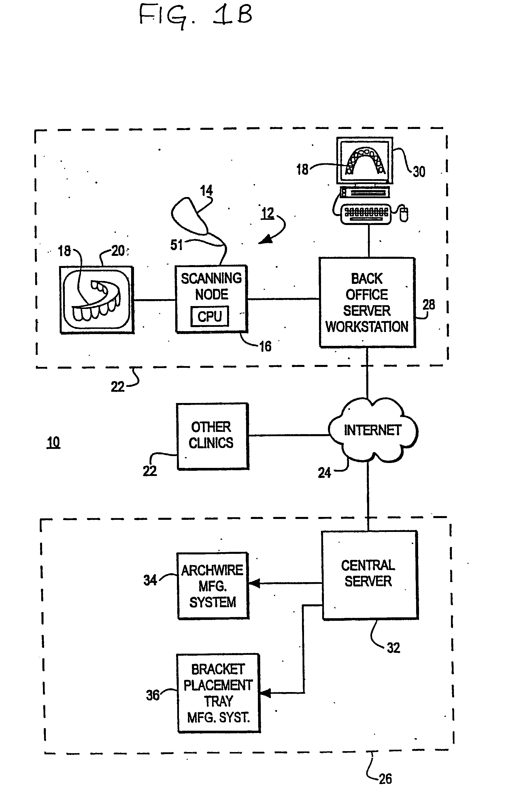
[0067] FIG. 1B is an illustration of an orthodontic care system 10 incorporating a scanner system 12. The scanner system 12 includes a hand-held scanner 14 that is used by the orthodontist or his assistant to acquire three-dimensional information of the dentition and associated anatomical structures of a patient. The images are processed in a scanning node or workstation 16 having a central processing unit, such as a general-purpose computer. The scanning node 16, either alone or in combination with a back-office server 28, generates a three-dimensional computer model 18 of the dentition and provides the orthodontist with a base of information for diagnosis, planning treatment, and monitoring care for the patient. The model 18 is displayed to the user on a monitor 20 connected to the scanning node 16.

[0068] The orthodontic care system consists of a plurality of orthodontic clinics 22 which are linked via the Internet or other suitable communications medium 24 (such as...


PUM


Abstract

Method and apparatus for registering an object of known predetermined geometry to scanned three dimensional data such that the object's location may be verified. Such a known object may comprise a less than ideal three-dimensional (3-D) digital object such as a tooth, a dental appliance (e.g., as a tooth bracket model) or other like object, including portions thereof. Knowledge of such an object's location is generally helpful in planning orthodontic treatment, particularly where the location of the object needs to be determined or confirmed or where incomplete or poor scan data is obtained. Aspects of the present invention provide methods of effectively verifying dental appliance location and displaying appliance locations using a computer and three-dimensional models of teeth.

Description

[0001] This application is a continuation-in-part application of the following pending U.S. patent applications:[0002] Ser. No. 09 / 835,007, filed Apr. 13, 2001;[0003] Ser. No. 09 / 835,039 filed Apr. 13, 2001;[0004] Ser. No. 09 / 560,131 filed Apr. 28, 2000;[0005] Ser. No. 09 / 560,583 filed Apr. 28, 2000;[0006] Ser. No. 09 / 560,645 filed Apr. 28, 2000;[0007] Ser. No. 09 / 560,644 filed Apr. 28, 2000;[0008] Ser. No. 09 / 580,133 filed Apr. 28, 2000.[0009] The entire contents of each of the above patent applications is incorporated by reference herein.[0010] A. Field of the Invention[0011] This invention relates generally to the fields of dentistry and orthodontics. More particularly, the invention relates to methods and apparatus for registering an object of known predetermined geometry to scanned three dimensional data such that the object's location in space may be verified. Such a known object may comprise a three-dimensional (3-D) digital object such as a virtual dental appliance (e.g., a ...

Claims


Application Information

Patent Timeline
Patent Type & Authority Applications(United States)
IPC IPC(8): A61B5/117A61C7/00A61B6/14A61C7/14A61C9/00A61C11/00A61C13/00A61F2/30G06T1/00G06T7/00G06T17/00G06T19/00H02K3/22H02K3/24H02K3/487H02K9/19
CPCA61B5/1178A61B5/4547A61C7/00A61C7/002A61C7/146A61C9/004A61C13/0004A61F2002/30953G06T7/0046G06T17/00G06T2207/30036H02K3/22H02K3/24H02K3/487H02K9/19A61C9/006G06T7/75B33Y50/00B33Y80/00
Inventor WEISE, THOMASRUBBERT, RUDGERIMGRUND, HANSSPORBERT, PEERMAETZEL, STEPHAN
Owner ORAMETRIX
Why Eureka
Try Eureka