Dental hand instrument and tip of the instrument

a hand instrument and hand tip technology, applied in dentistry, dental tools, medical science, etc., can solve the problems of inability to reach difficult places, inability to have the entire hand instrument made of transparent elastic material, unpractical hand instruments, etc., and achieve the effect of the same firmness and working precision

Inactive Publication Date: 2003-01-30
LM INSTRUMENTS OY
View PDF13 Cites 25 Cited by
  • Summary
  • Abstract
  • Description
  • Claims
  • Application Information

AI Technical Summary

Benefits of technology

0011] The invention combines the best qualities, such as thinness, ductility and stiffness, of a neck part made from a high-strength metal, such as steel, with the best qualities of another material of the tip, which are needed in relevant clinical work. Thus, the tip can be replaced as required with another one that is best suited for the work on hand in respect of tool shape and material.
0012] The replaceable tips are connected to the ends of the neck

Problems solved by technology

Often, however, it is not possible to have the entire hand instrument made of transparent and elastic material because the instrument would be too flexible.
However, such a hand instrument is unpractical because the forceps-like structure is clumsy.
With a tip mounted transversely on the end of the handle it is not possible

Method used


Image

  • Dental hand instrument and tip of the instrument
  • Dental hand instrument and tip of the instrument
  • Dental hand instrument and tip of the instrument

Examples


second embodiment

[0016] the hand instrument of the invention is characterized in that the axial socket of each neck part of the hand instrument has at least two slots extending in the longitudinal direction of the socket so that each coupling element has two opposite spring-like tongues which squeeze the projection of the tip between them.

[0017] A third preferred embodiment of the hand instrument of the invention is characterized in that the interior surfaces of the socket-like coupling elements of the neck parts have a circular or cornered cross-sectional form.

[0018] A fourth preferred embodiment of the hand instrument of the invention is characterized in that the interior surfaces of the socket-like coupling elements of the neck parts have a quadrangular or hexagonal cross-sectional form.

[0019] A fifth preferred embodiment of the hand instrument of the invention is characterized in that the coupling elements forming an extension of the neck parts comprise projections onto which the socket parts co...

examples of embodiments

[0034] In the following, the invention will be described by the aid of examples with reference to the attached drawings, wherein

LIST OF ILLUSTRATIONS

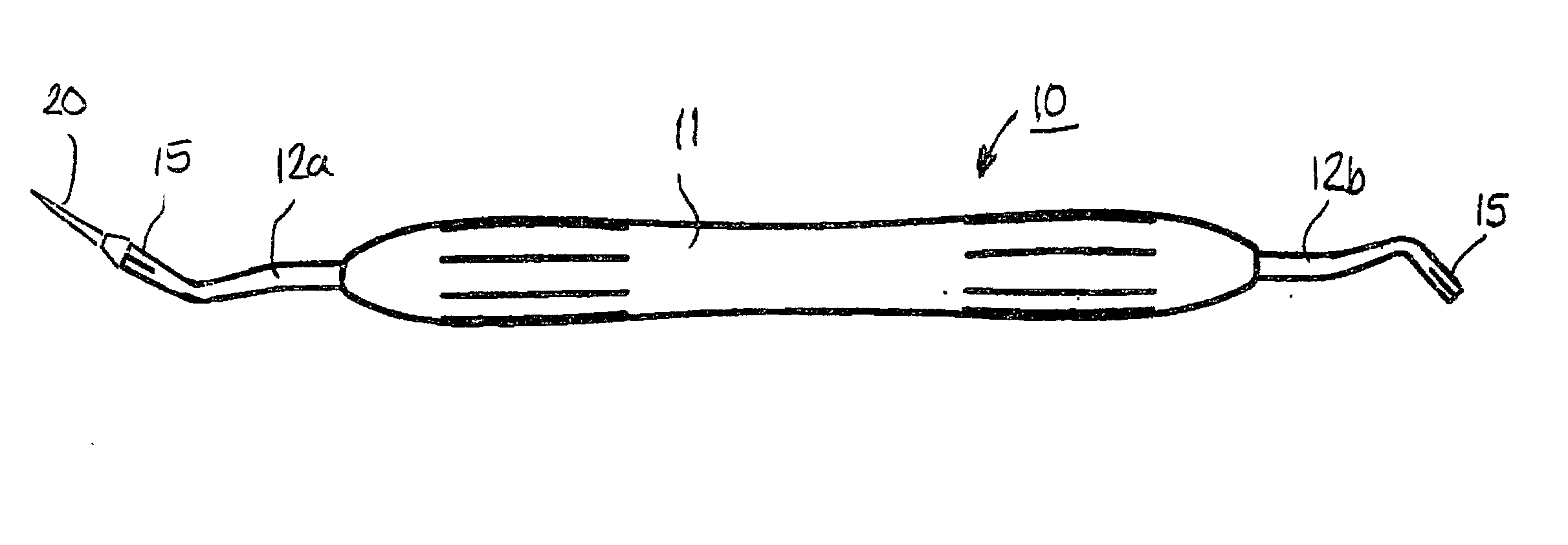
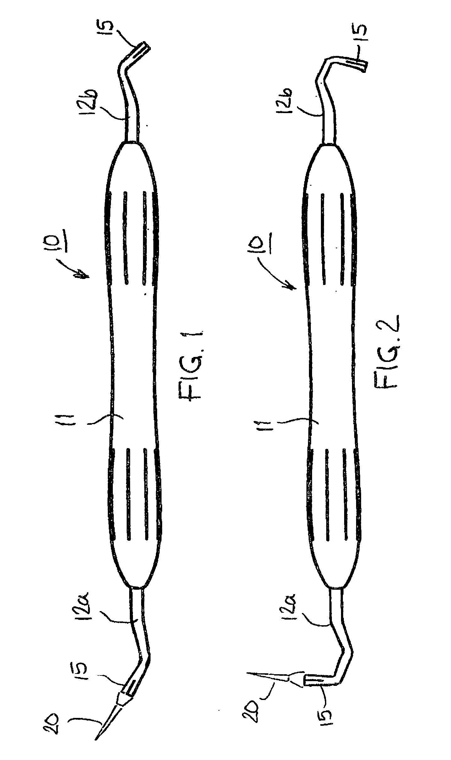
[0035] FIG. 1 presents a side view of an instrument according to the invention.

[0036] FIG. 2 corresponds to FIG. 1 and presents a second embodiment of the hand instrument.

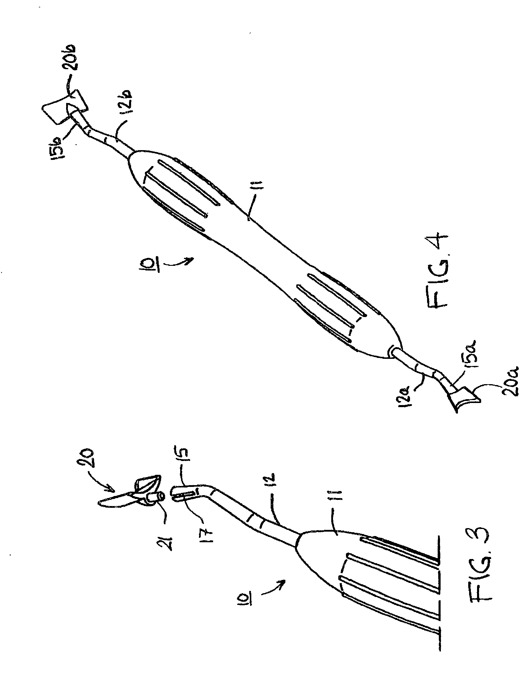
[0037] FIG. 3 presents an axonometric view of one end of the hand instrument and a tip to be attached to it.

[0038] FIG. 4 presents an axonometric view of a hand instrument with a detachable tip attached to each end.

[0039] FIG. 5 presents a sectioned side view of a coupling element connected to the end of the neck part.

[0040] FIG. 6 presents a section of FIG. 4, taken along line VI-VI.

[0041] FIG. 7 corresponds to FIG. 5 and presents a tip provided with a locking flange, connected to the coupling element of the neck part.

[0042] FIG. 8 presents a side view of a tip of the hand instrument, provided with a locking flange.

[0043] FIG. 9 corresponds to FIG. 8 and presents a se...

third embodiment

[0044] FIG. 10 corresponds to FIG. 8 and presents the tip.

[0045] FIG. 11 presents an axonometric view of the tip shown in FIG. 8.


PUM


Abstract

A dental hand instrument (10), comprising a handle (11) with parts (12a, 12b) at its ends. The end of each neck part is provided with a coupling element (15) designed for the connection of replaceable tips (20) and oriented in the same direction with the neck part. The coupling element is a socket or pin (19) extending in the same direction with the neck part and allowing a corresponding concentric pin (21) or socket (26) of the tip to be fitted into/onto it. The socket of the coupling element may be provided with slots (17), and the inner surface of the socket has a circular or cornered cross-sectional form. The neck part and coupling element of the hand instrument are preferably made of stainless steel and the tip is made of steel, aluminun, plastic-coated aluminum, steel or titanium.

Description

SUBJECT OF THE INVENTION[0001] The invention relates to a hand instrument for use in dental care, comprising a handle having at each end of it a narrower neck part, preferably made of a high-strength metal such as steel, each neck part being provided with a tip forming a tool for dental care.STATE OF THE ART[0002] A dental hand instrument usually comprises a handle with a dental tool at least at one end of it. The handle may be made of metal, such as stainless steel, or a hard plastic material. However, the handle may also have a metal core coated with a softer material, such as silicone rubber. The handle and the tool are usually connected by neck parts bent in various ways to allow the tool to be applied even to difficult places, such as e.g. the hind surfaces of teeth. The neck part and the tool are generally joined to each other and made of the same material, e.g. stainless steel. The tool at the end of the hand instrument is e.g. a spicular feeler or a gingival pocket gauge, a ...

Claims


Application Information

Patent Timeline
IPC IPC(8): A61C3/00
CPCA61C3/00
Inventor KANGASNIEMI, PEKKALUMME, EINOLEHTONEN, KARI
Owner LM INSTRUMENTS OY
Why Eureka
Try Eureka