
Abrasive product and method of making and using the same

a technology of abrasive products and abrasives, which is applied in the direction of flexible wheel, metal-working apparatus, manufacturing tools, etc., can solve the problems of preventing the proper cure of precursor polymer subunits, patterned abrasive coatings, and abrasive granules having a specified pattern on the backing

Inactive Publication Date: 2003-01-30
3M INNOVATIVE PROPERTIES CO
View PDF0 Cites 108 Cited by
  • Summary
  • Abstract
  • Description
  • Claims
  • Application Information

AI Technical Summary

Benefits of technology

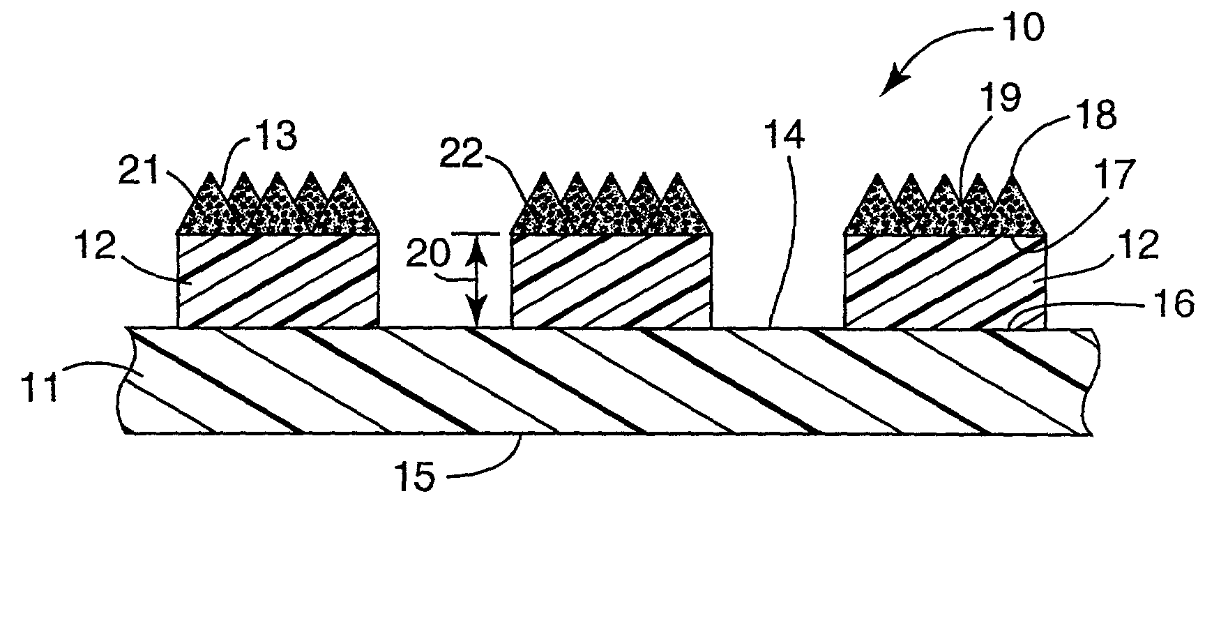
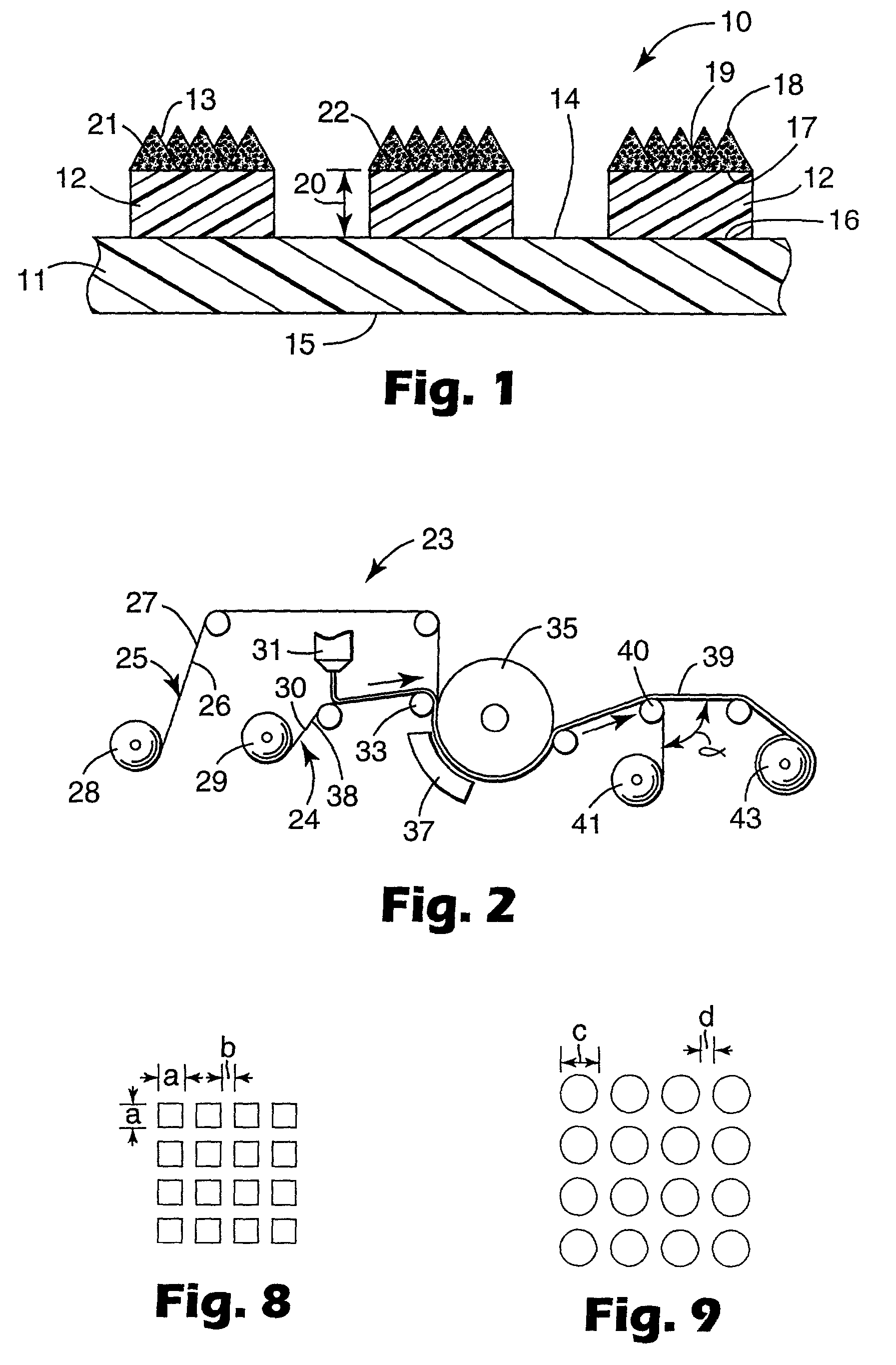
[0064] The abrasive product of the present invention has a long useful life because of the existence of spaces between the shaped bodies which provides a collection area for swarf and debris generated during finishing. Thus, the abrasive product can use very fine abrasive grains to provide extremely fine surface finishes to any of a variety of workpiece surfaces. The product of the invention provides a viable replacement for utilizing loose abrasive slurries and obviates the need for liquid handling equipment normally associated with slurries and the need for finding appropriate disposal sites for used slurries. The presence of the recessed areas between the shaped bodies that are coated with shaped abrasive coatings provides for efficient fluid flow at the working face of the abrasive product of the invention without undesirable "stiction" which is normally encountered in smooth-surfaced lapping films on smooth-surfaced workpiece surfaces. Compared to a planar backing, the shaped backing transfers higher grinding pressure to the workpiece, thereby increasing the rate of finish refinement. The products of the invention, having a shaped-surface, provide for controlled breakdown of the abrasive layer which provides for a constant cut rate and extended use life of the abrasive coating.

Problems solved by technology

The mold has patterned cavities therein which result in the abrasive granules having a specified pattern on the backing.
The presence of the grid results in a patterned abrasive coating.
In some instances, certain abrasive particles and / or certain additives will absorb ultraviolet and visible light, which may hinder proper cure of the precursor polymer subunits.
In general, the addition of the plasticizer will increase the erodibility of the abrasive composite and soften the overall binder composition.
An abrasive composite structure with a cross section that is larger at the distal end than at the back may also be used, although fabrication may be more difficult.
If excessive heat is generated, this may distort or melt the thermoplastic tooling.
Since the precursor polymer subunits are not cured while in the cavities of the production tool, this results in the curable abrasive composite layer flowing and distorting the abrasive composite shape.

Method used


Image

  • Abrasive product and method of making and using the same
  • Abrasive product and method of making and using the same
  • Abrasive product and method of making and using the same

Examples


example 1

[0200] Pre-mix #1: 60.8 parts CN973J75, 36.4 parts SR339 and 2.8 parts TPO-L were combined using a mixer, available under the trade designation DISPERSATOR from Premier Mill Corp., Reading, Pa., at room temperature until air bubbles had dissipated.

[0201] Slurry #1: 3.4 parts of pre-expanded F80 was then added to 96.6 parts of Pre-mix #1 and formed into homogeneous slurry #1 using the DISPERSATOR mixer. F80 microspheres were pre-expanded at 160.degree. C. for 60 minutes before use.

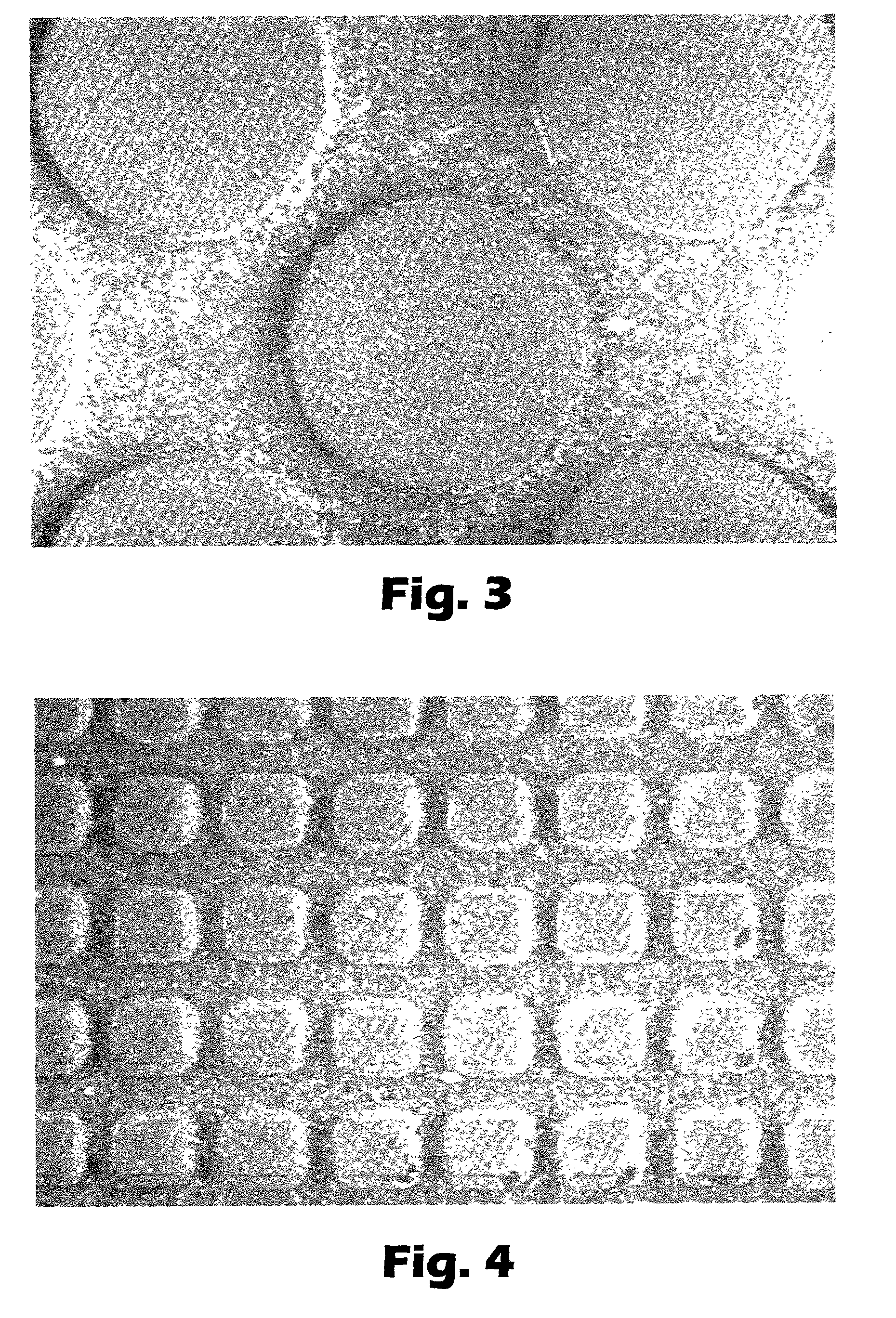
[0202] Slurry #1 was then applied, via hand spread, to a microreplicated tooling having square posts, 1.3 mm.times.1.3 mm.times.0.356 mm deep, with a 22% bearing area, as described in Table 3. The slurry filled tooling was then laminated face down to the smooth side of corona treated backing available from Minnesota Mining and Manufacturing Company (3M) under the trade designation 3M HOOK-IT II.TM. backing by passing through a set of rubber nip rolls at 26 cm / min. and a nip pressure of 275 kPa (40 psi). The...

example 2

[0206] A 3-dimensional abrasive coating on top of 3-dimensional foam structure was prepared as outlined in Example 1, wherein slurry #1 was applied to a microreplicated tooling having the same square posts but with a 32% bearing area, as described in Table 3.

example 3

[0207] A 3-dimensional abrasive coating on top of 3-dimensional foam structure was prepared as outlined in Example 1, wherein slurry #1 was applied to a microreplicated tooling having the same square posts but with a 42% bearing area, as described in Table 3.


PUM

PropertyMeasurementUnit
particle sizeaaaaaaaaaa

Abstract

The present invention relates to an abrasive article having a shaped abrasive coating on a shaped backing and to a method of making and using the flexible abrasive article. The flexible abrasive article includes a backing bearing separated, shaped non-abrasive structures having a distal end spaced from the backing which are coated with a shaped abrasive coating. The method comprises providing the backing, applying to one surface of the backing a plurality of separated, shaped non-abrasive structures with distal ends, coating the distal ends with a curable composition containing abrasive particles, imparting a shaped configuration to the uncured coating and curing the coating.

Description

[0001] This is a continuation-in-part of U.S. patent application Ser. No. 09 / 850,661, filed May 7, 2001, incorporated herein by reference.[0002] The present invention relates generally to abrasive articles having a shaped abrasive coating on a non-abrasive shaped backing and to a method of making and using the abrasive article.[0003] In the abrasive industry there is a trend to finer and finer surface finish. Naturally, to achieve these finer surface finishes, smaller sized abrasive particles are employed in the abrasive article. In some instances the particle size of these small sized abrasive particles is less than 50 .mu.m, typically less than 25 .mu.m and sometimes less than 10 .mu.m. In some instances loose abrasive slurries are employed rather than using fixed abrasive articles where the abrasive particles may be bonded together (to provide a bonded abrasive product) or to a backing (to provide a coated abrasive product). Many years ago, these loose abrasive slurries were capa...

Claims


Application Information

Patent Timeline
Patent Type & Authority Applications(United States)
IPC IPC(8): B24D3/26B24D3/32B24D11/00B24D13/14
CPCB24D3/26B24D3/32B24D11/001B24D13/147
Inventor ANNEN, MICHAEL J.SCHUTZ, JAMES W.
Owner 3M INNOVATIVE PROPERTIES CO
Learn More