Method for manufacturing shaft member and method for manufacturing dynamic pressure bearing device

a technology of dynamic pressure bearing and shaft member, which is applied in the direction of sliding contact bearings, manufacturing tools, mechanical equipment, etc., can solve the problems of significant restrictions in the height of dynamic pressure bearing devices, the risk of declining the reduction of the bonding strength of thrust plates 3

Inactive Publication Date: 2003-02-06
SANKYO SEIKI MFG CO LTD
View PDF0 Cites 7 Cited by
  • Summary
  • Abstract
  • Description
  • Claims
  • Application Information

AI Technical Summary

Benefits of technology

[0010] According to such a method for manufacturing the shaft member, the member to be fixed is firmly fixed by the tightening force of the screw member against the shaft, which greatly increases the bonding strength of the member to be fixed.
[0019] Moreover, in the method for manufacturing the dynamic pressure bearing device, due to the fact that a space section is provided where the thrust plate and the screw member join with each other in order to reduce the capillary force in the screwing section between the screw member and the shaft member and thereby prevent the adhesive from leaking outside, the adhesive is well prevented from leaking outside when it is injected.

Problems solved by technology

However, in recent years, there has been a trend for the height of dynamic pressure bearing devices to be significantly restricted in the axial direction as the demand for thinner devices grew, which has led to a reduction in the joining length in the axial direction of the thrust plate 3 to the rotary shaft 2, which in turn has led to a risk of declining bonding strength of the thrust plate 3.
A reduction in the bonding strength of the thrust plate 3 is becoming a major issue, especially in devices such as mobile devices whose uses are premised upon portability that require sufficient impact resistance in case such devices are dropped.
Once the foreign matters have accumulated in the hole bottom section of the female screw section 2a, they cannot be completely removed even after a cleaning process is performed; and if such foreign matters were to scatter outside while the device is in use, they can, for example, become attached to recording disks, which requires cleanliness, thereby possibly causing fatal defects such as failure to record and / or reproduce information.
This, however, causes great stress on the tapping tool that makes the tapping tool prone to breaking, which can reduce productivity.
This problem also occurs when the thrust plate 3 is provided in the upper section in the axial direction so that the thrust plate 3 is used simply as a fall-out stopper plate for the shaft.

Method used


Image

  • Method for manufacturing shaft member and method for manufacturing dynamic pressure bearing device
  • Method for manufacturing shaft member and method for manufacturing dynamic pressure bearing device
  • Method for manufacturing shaft member and method for manufacturing dynamic pressure bearing device

Examples


Embodiment Construction

[0031] An embodiment of the present invention, along with an overall structure of a hard disk drive device (HDD) to which the manufacturing method according to the present invention has been applied, is described in detail below with reference to the accompanying drawings.

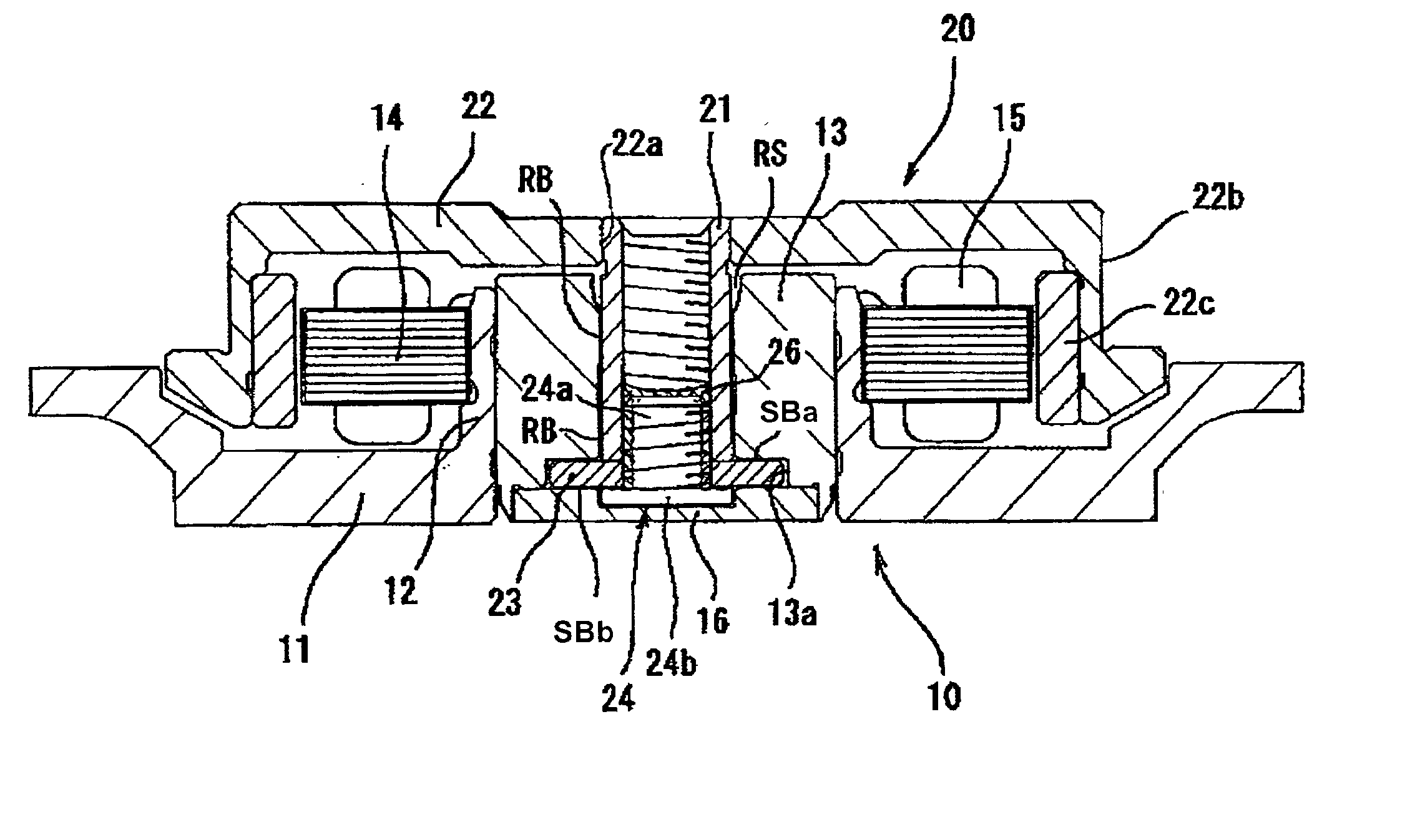
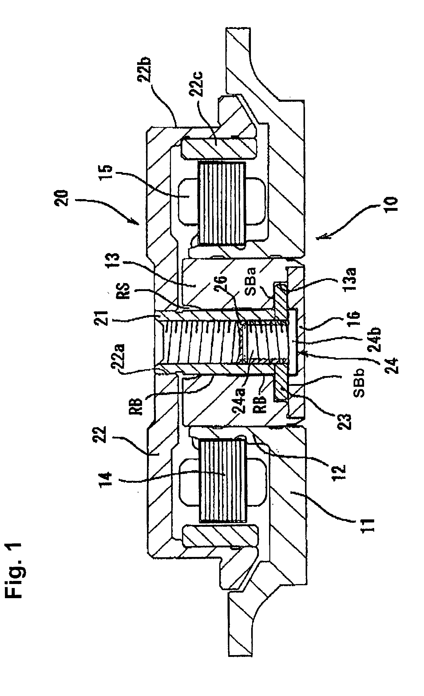
[0032] FIG. 1 shows an overall view of a HDD spindle motor of a shaft rotation type. The HDD spindle motor includes a stator assembly 10, which is a fixed member, and a rotor assembly 20, which is a rotating member assembled onto the top of the stator assembly 10. The stator assembly 10 has a fixed frame 11, which is screwed to a fixed base omitted from drawings. The fixed frame 11 is formed with an aluminum material to achieve a lighter weight; on the inner circumference surface of a ring-shaped bearing holder 12 formed upright in the generally center part of the fixed frame 11 is a bearing sleeve 13, which is a fixed bearing member formed in the shape of a hollow cylinder and joined to the bearing holder 12 throu...


PUM

PropertyMeasurementUnit
viscosityaaaaaaaaaa
viscosityaaaaaaaaaa
temperatureaaaaaaaaaa

Abstract

A method for manufacturing a dynamic pressure bearing device is provided. The dynamic pressure bearing device includes a bearing member and a shaft member rotatably disposed with respect to one another, and a thrust plate mounted on the shaft member and a counter plate fixed to the bearing member disposed opposite to one another to compose a thrust dynamic pressure bearing section. According to the method, a through hole that communicates with both ends of the shaft member in an axial direction thereof is formed in the shaft member, and a female screw section is formed in an inner wall section of the through hole such that screw members can be screwed from the both ends of the through hole of the shaft member. One of the screw members is screwed in the through hole of the shaft member from one end of the shaft member. The screw member has a screw head section and a male screw section extending from the screw head section for threaded engagement with the female screw section. Prior to screwing the screw member in the through hole of the shaft member, the thrust plate is interposed in the axial direction between the screw head section of the screw member and the one end of the shaft member, and the thrust plate is fixed to the shaft member by tightening the screw member. An adhesive is injected to fill gaps in a screw engagement section between the male screw section of the screw member and the female screw section of the shaft to prevent lubrication fluid from leaking through the screw engagement section, wherein the adhesive has a viscosity of 5 Pa.s or higher after the coating.

Description

[0001] The present invention relates to a method for manufacturing shaft members and a method for manufacturing dynamic pressure bearing devices, in both of which another member is affixed to the shaft member.DESCRIPTION OF RELATED ART[0002] In general, various types of member are fixed to shafts in a variety of devices. For example, in a dynamic pressure bearing device used in a hard disk drive (HDD) device, such as the one shown in FIG. 10, a rotary shaft (a shaft member) 2 is inserted into a bearing sleeve (bearing member) 1, which is the fixed member, in a freely rotatable manner, and radial bearing sections RB in two places separated in an axial direction are formed by having a lubricating fluid such as an oil injected into a minuscule gap between the inner circumference surface of the bearing sleeve 1 and the outer circumference surface of the rotary shaft 2.[0003] The lubricating fluid is filled continuously from the radial bearing sections RB into a gap between one of the tw...

Claims


Application Information

Patent Timeline
Patent Type & Authority Applications(United States)
IPC IPC(8): F16C3/03F16C17/04F16C33/10
CPCF16C17/04Y10T29/49947F16C33/107F16C17/045
Inventor GOMYO, MASATO
Owner SANKYO SEIKI MFG CO LTD
Why Eureka
Try Eureka