
Method and device for notifying server failure recovery

Inactive Publication Date: 2003-02-06
FUJITSU LTD
View PDF7 Cites 41 Cited by
  • Summary
  • Abstract
  • Description
  • Claims
  • Application Information

AI Technical Summary

Benefits of technology

[0023] Thus, it becomes possible for the client which knows that the notification is received when the failure has recovered, or its operator to reliably access the server after having received the failure recovery notification without repeatedly trying a useless access to the server inaccessible for a failure occurrence.
[0024] Also, the failure recovery notification has only to be given to the client having tried to access during the failure occurrence, thereby enabling the trouble of notifying all of the clients which may use the server to be eliminated.

Problems solved by technology

However, the client or its operator can not recognize when the server, to which the access was tried, is powered up or the failure is recovered.
This re-access operation is required to be performed until the server is accessed, which is a very troublesome operation for the user and causes an increase of a network load.
However, generally, only a network manager uses the SNMP manager, so that client's user, requiring to know the recovery state of the server most, does not know the fact until the notification from the network manager is obtained.
However, in this method and the device for monitoring the client-server system, the failure or the recovery of the system is not notified to the client of the client-server system in which the failure has occurred, requiring to know the failure / recovery state of the server most.
Thus, the method of giving the failure recovery notification, when the server has recovered from a failure, to all of the clients registered in the list is cumbersome because the recovery notification it to be transmitted to even a client which is not going to use the server, and has not been practical since the number of users to whom the failure recovery notification is transmitted becomes too large in an open server and the like which may be used by numerous persons.
However, in this method, the load of the representative client is increased, and additionally the client having tried but failed to access the server has to register itself in the representative client as a standby client.

Method used


Image

  • Method and device for notifying server failure recovery
  • Method and device for notifying server failure recovery
  • Method and device for notifying server failure recovery

Examples


embodiment (

[0350] [5] Embodiment (5): Server Failure Detection by Presence / Absence of Return IP Packet, Inquiry of Necessary / Unnecessary of Server Failure Recovery Notification, and Inquiry of Mail Address Through Pseudo Connection

[0351] Hereinafter, an embodiment (5) of the server failure recovery notification device 100 according to the present invention will be described. The arrangement of the server failure recovery notification device 100 of the embodiment (5) is the same as the that of the embodiment (4) shown in FIG. 26, and the network arrangement to which the device 100 is applied is the same as that of the embodiment (4) shown in FIG. 27.

[0352] In the process procedure example of the embodiment (4) shown in FIGS. 30 and 31, the data (HTTP request signal 853) indicating "necessary / unnecessary of the failure recovery notification mail" and "mail address of the operator of the client" are directly transmitted to the message transceiver 15 of the server failure recovery notification dev...


PUM


Abstract

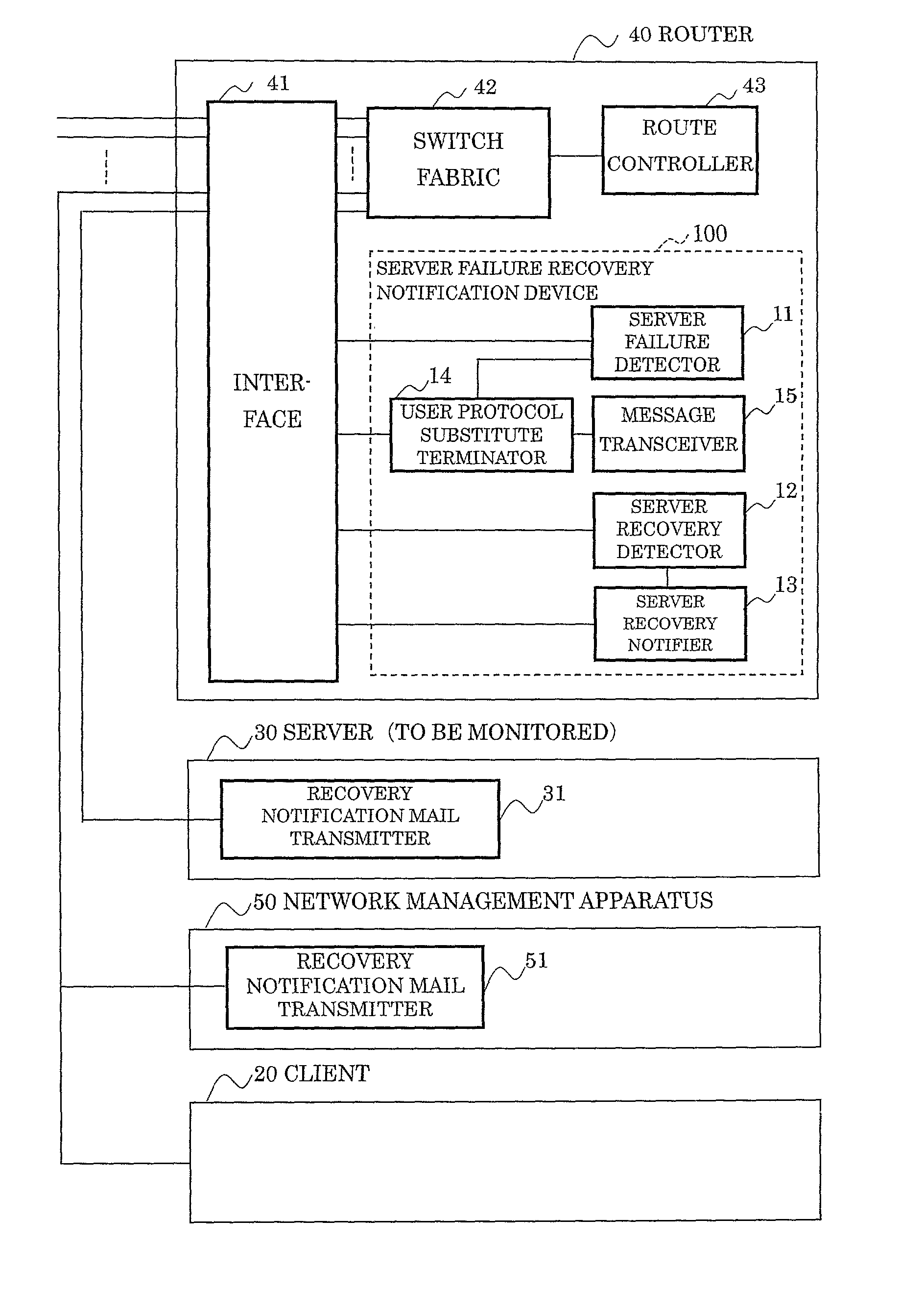
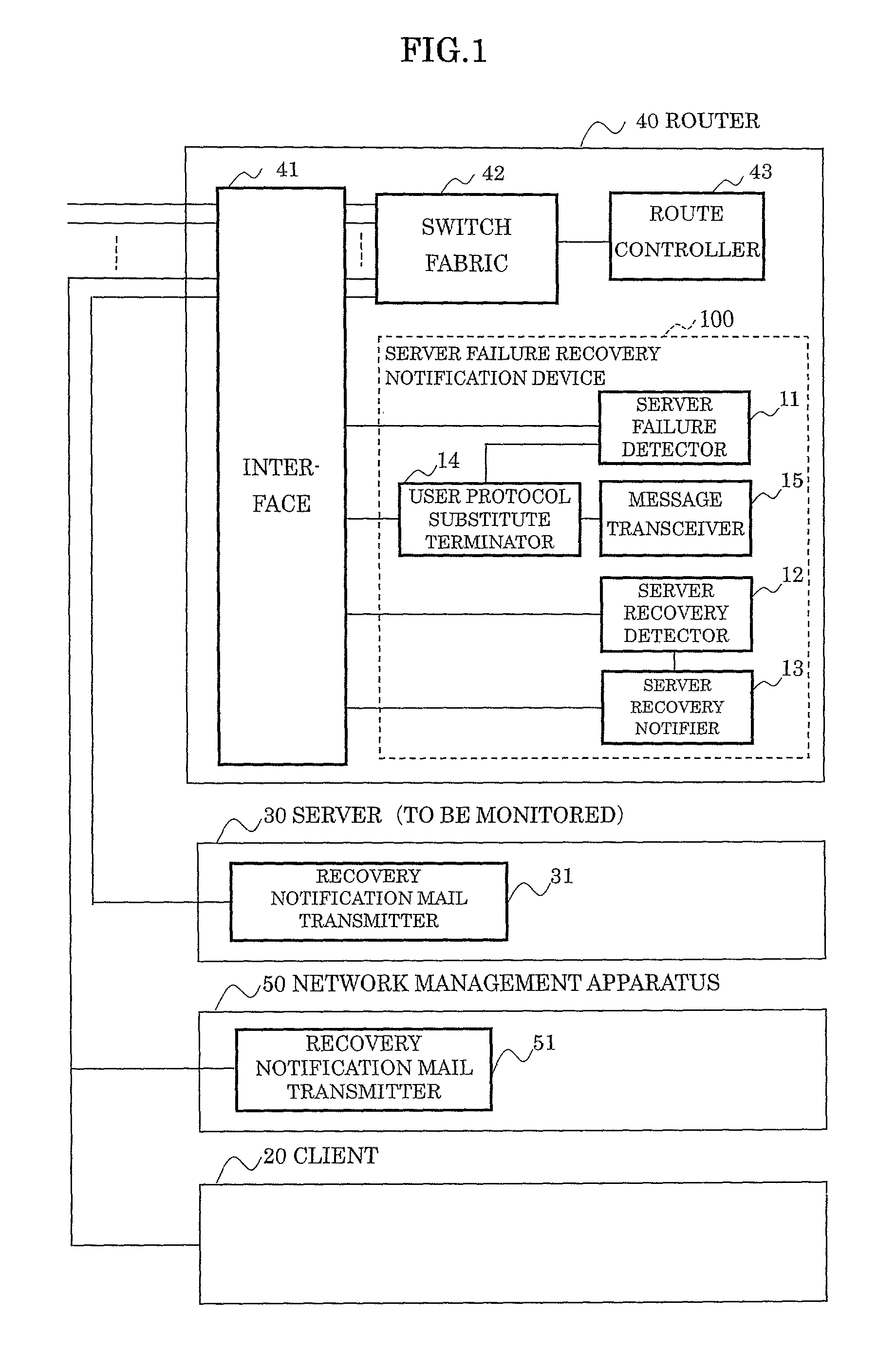
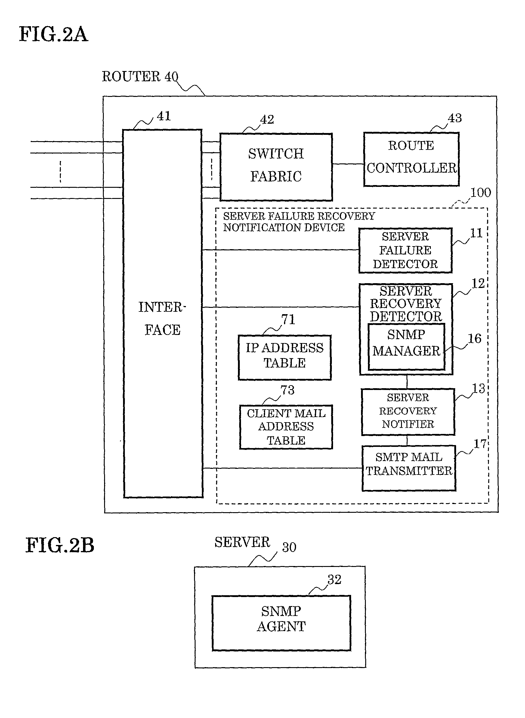
In a method and a device for notifying a server failure recovery which notify a failure recovery of a server or the like to a client, a server failure detector detects a client having tried but failed to access a server due to a failure, a server recovery detector detects a failure recovery, and a server recovery notifier gives a failure recovery notification to the client having failed to access. Also, the server failure recovery notification device is mounted on a router. The server failure detector detects the client having failed to access based on a destination unreachable message of an ICMP of the router 40, or detects the client having failed to access by determining the failure is being occurred in the server, in the absence of a reply IP packet to the IP packet addressed to the server from the client.

Description

[0001] 1. Field of the Invention[0002] The present invention relates to a method and a device for notifying a server failure recovery, and in particular to a method and a device for notifying a server failure recovery which notify a failure recovery of a server and the like to a client.[0003] Recently, the Internet and an intranet have become widespread over all industrial fields and social systems including general homes.[0004] In the Internet and the intranet, a client can easily download information of text, graphic, image, voice, and the like from e.g. a web server and file information from an FTP (File Transfer Protocol) server.[0005] In such an information transmission between the client and the server, when a failure occurs at the server, it is necessary to notify the occurrence and the recovery of the failure to the client.[0006] 2. Description of the Related Art[0007] When a client tries to access a server by transmitting a packet requesting a connection (access) thereto an...

Claims


Application Information

Patent Timeline
IPC IPC(8): G06F11/30G06F13/00G06F15/00H04L69/40
CPCH04L12/58H04L29/1215H04L41/0654H04L61/1564H04L67/42H04L69/16H04L69/40H04L69/329H04L61/4555H04L51/23H04L51/00H04L67/01
Inventor SUZUYAMA, SHIGERUIWAHASHI, TADASHI
Owner FUJITSU LTD
Learn More