Method and apparatus for molding components with molded-in surface texture

a technology of surface texture and molding method, applied in the field of automobile manufacturing industry, can solve the problems of visually unacceptable parts which must be scrapped, and high rejection and discard rate of such parts

Inactive Publication Date: 2003-02-13
HERBERT OLBRICH
View PDF21 Cites 90 Cited by
  • Summary
  • Abstract
  • Description
  • Claims
  • Application Information

AI Technical Summary

Problems solved by technology

On the other hand, if the intended surface texture is inaccurately or distortedly reproduced on the surface of the molded part, this results in a visually unacceptable part which must be scrapped.
Thus, it has been a significant problem in the industry, that defective or unacceptable surface texturing leads to a rather high reject and discard rate of such parts, although the parts may otherwise be fully in conformance with other requirements.
If has also been extremely difficult or impossible up to the present time, to achieve complex, or finely detailed surface textures, without distortion or misrepresentation, using conventionally known methods.
Thus, a regular geometric pattern of dots or lines or the like on the starting cover sheet material will clearly show the areas of distortion resulting from the three-dimensional molding, and will generally not be acceptable.
Such a technique is generally only suitable for random textures of which a distortion is not readily apparent, or for providing a texture on areas that are not strongly contoured.
Another problem of such a conventional process arises when the textured surface of the cover sheet is pressed in contact with a flat surface of a mold.
In such a case, the surface texture will be at least partially crushed or flattened or "ironed out", so that any resulting surface texture cannot have a very strong or roughly profiled texture.
Such techniques are complicated, time consuming and not economical in production.
These slash skin methods are rather complicated, time consuming, and costly due to several additional required steps.
Moreover, these processes generally use polyvinyl chloride and polyurethane materials, which are becoming ever more undesirable because they are not easily recycled, and they represent toxic risks and disposal problems.
Also, the thin mold sheets have a relatively short useful life cycle, which leads to high tooling costs, and the surface textures that can be achieved are limited.
Also, the conventional patterning or texturing processes all involve additional steps and additional work effort, beyond the molding operation itself.
However, since the foam backing is a closed-cell foam that is not permeable through its thickness, the extent of absorption of the viscous liquid skin film material into the foam backing is limited to the interface surface.

Method used


Image

  • Method and apparatus for molding components with molded-in surface texture
  • Method and apparatus for molding components with molded-in surface texture
  • Method and apparatus for molding components with molded-in surface texture

Examples


Embodiment Construction

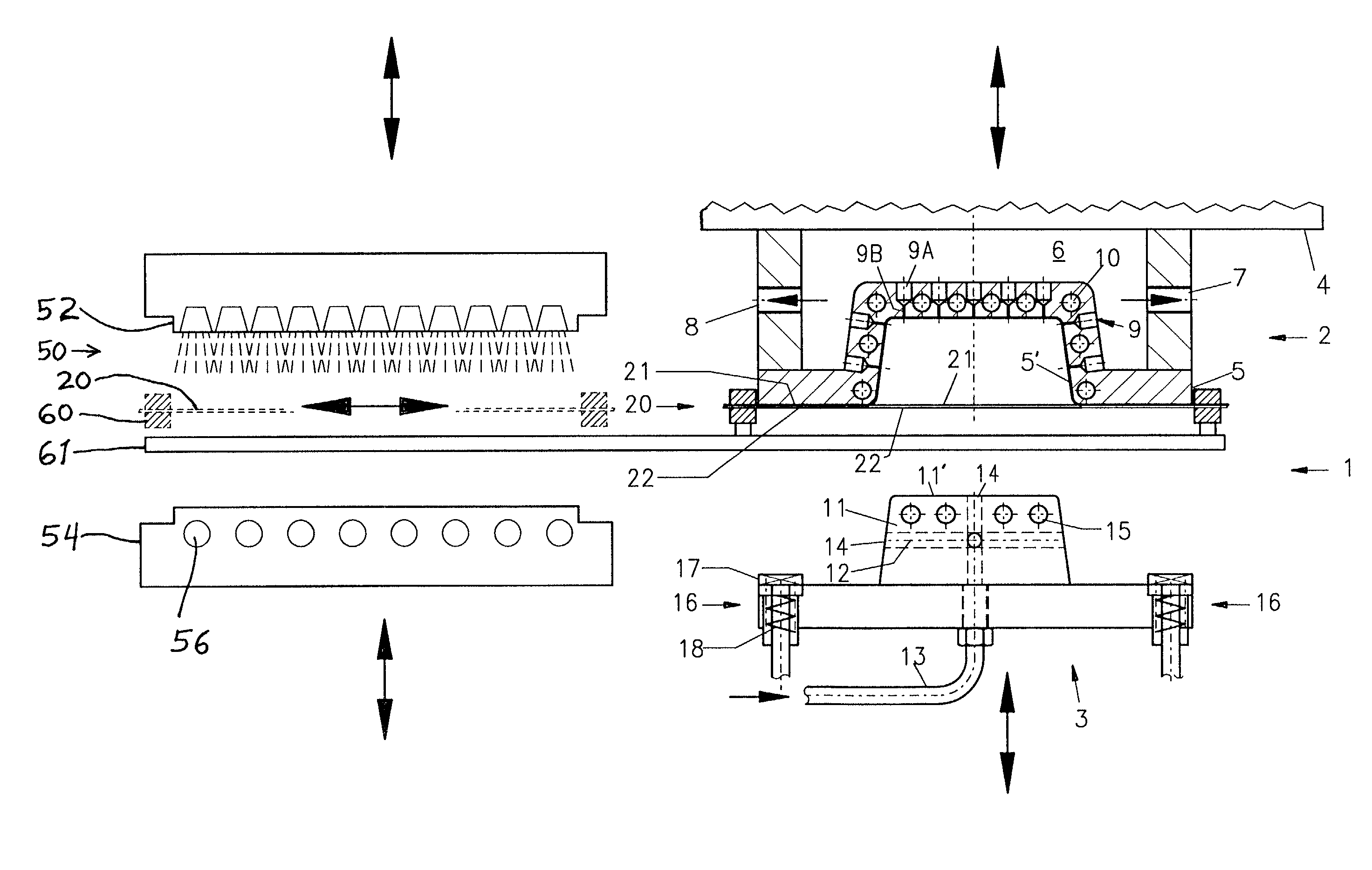
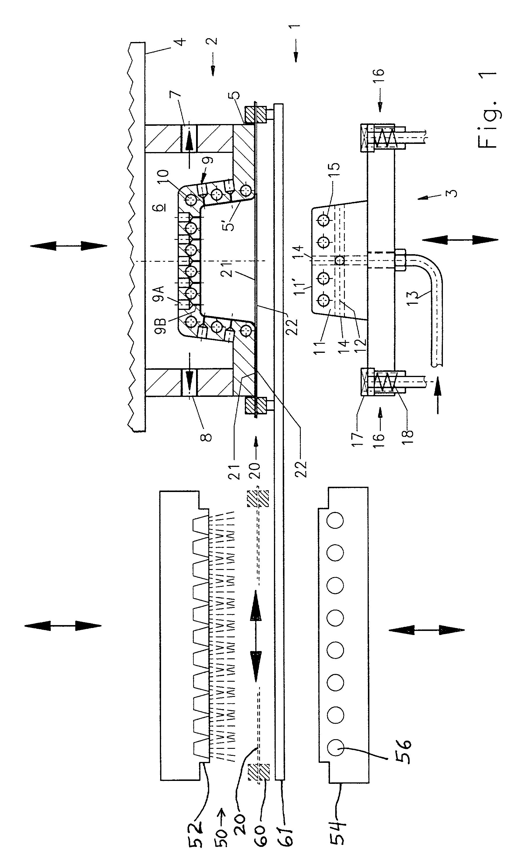
[0026] FIG. 1 schematically shows a forming line according to the invention, including a heater arrangement 50 and a molding apparatus 1, as well as a cover sheet transfer carriage primarily including a clamp frame 60. The clamp frame 60 holds and carries a cover sheet 20 including a skin film 21 on a foam backing 22. The clamp frame 60 moves along transport rails 61 to thereby transport the cover sheet 20 into the heater arrangement 50, holds the cover sheet 20 while it is heated there, and then further moves along the rails 61 to transport the heated cover sheet into position in the molding apparatus 1.

[0027] The heater arrangement 50 in this embodiment preferably includes an infrared heater array 52 arranged above the plane of the clamp frame 60, and a tempering contact plate 54 arranged below the plane of the clamp frame 60. The tempering contact plate 54 is, for example, a metal plate 54 that is cooled by a cooling liquid flowing through coolant passages 56 therein. The heater ...


PUM

PropertyMeasurementUnit
atmospheric pressureaaaaaaaaaa
pressureaaaaaaaaaa
pressureaaaaaaaaaa

Abstract

An automobile interior trim component includes a molded substrate laminated onto a cover sheet including a foam backing and a skin film having a surface texture. The cover sheet is preheated so the skin film is in a melted viscous liquid state above its melting temperature, and the foam backing remains in a solid elastic foam state below its melting temperature. The preheated cover sheet is mechanically pre-molded by a back mold into a front mold. Pressurized air is applied through the back mold, to blow-mold the cover sheet against the front mold, so the melted skin film reproduces a surface texture of the front mold surface while the solid foam backing acts as a buffer and air barrier layer. Vacuum is applied through the front mold surface. The mold is opened, a substrate is introduced, and the back mold then molds and thermally laminates the substrate against the foam backing of the cover sheet.

Description

[0001] The invention relates to a method of manufacturing molded parts, such as automobile interior trim components, that have a molded-in surface texture, as well as an apparatus for carrying out such a method.BACKGROUND INFORMATION[0002] In various technical fields, and particularly in the automobile manufacturing industry, there is a constantly growing demand for various molded parts that have a surface texture molded into or onto the surfaces of such parts. For example, it is increasingly desired to provide interior trim components of a motor vehicle, such as headliners, door trim insert panels, column trim covers, consoles, parcel shelves, dashboards, and the like, with a surface texture such as an artificial leather grain, an artificial wood-like grain, a pattern of dots or lines or the like, simulated stitching lines, raised bumps and indented depressions or even molded-in text or logos. Such surface textures enhance the appearance of the visible surface of the molded part, o...

Claims


Application Information

Patent Timeline
Patent Type & Authority Applications(United States)
IPC IPC(8): B29C33/10B29C33/12B29C33/38B29C37/00B29C43/18B29C43/20B29C43/36B29C43/52B29C43/56B29C51/10B29C51/14B29C51/16B29C51/26B29C51/42B29C59/02B29L9/00
CPCB29C37/0032B29L2031/3041B29C43/183B29C43/36B29C51/14B29C51/16B29C51/262B29C51/423B29C59/026B29C2043/3411B29C2043/3602B29C2791/001B29C2791/006B29C2791/007B29K2105/04B29L2009/001B29L2031/3005B29C43/00B29C2949/3094B29C59/02
Inventor SPENGLER, ERNST MAXIMILIAN
Owner HERBERT OLBRICH
Why Eureka
Try Eureka