
Apparatus for energizing a remote station and related method

a technology for energizing remote stations and apparatus, applied in applications, instruments, therapy, etc., can solve problems such as lack of such systems

Inactive Publication Date: 2003-02-13
PITTSBURGH UNIV OF
View PDF0 Cites 75 Cited by
  • Summary
  • Abstract
  • Description
  • Claims
  • Application Information

AI Technical Summary

Benefits of technology

[0018] The system eliminates the need for batteries on the remote station or the use of hard wired systems.
[0022] It is another object of the present invention to provide such a system wherein the remote station is not required to contain an energy storage device, such as a battery, or to be part of a hard wired or printed circuit system.
[0026] It is another object of the present invention to provide such a system wherein the remote station may be miniaturized and does not require frequent maintenance.
[0028] It is a further object of the present invention to provide such a system wherein use on miniaturized Systems on a Chip (SOC) is facilitated.
[0030] It is a further object of the present invention to provide such systems which may be employed effectively in Radio Frequency IDentification (RFID) devices.

Problems solved by technology

There is also lacking such systems wherein the remote unit may be miniaturized so as to have numerous potential uses.

Method used


Image

  • Apparatus for energizing a remote station and related method
  • Apparatus for energizing a remote station and related method
  • Apparatus for energizing a remote station and related method

Examples


case 1 case 2

1 Case 1 Case 2 Effective area, A.sub.e 8.349 .times. 10.sup.-4 meter.sup.2 12.242 .times. 10.sup.-4 meter.sup.2 Electric Field Strength, 55.52 volts 67.2 volts .vertline.E.sub.TB.vertline.

[0119] Based on the relatively close agreement of the above results, the antenna effective area is at least 8.349.times.10.sup.-4 meter.sup.2. From the chip dimensions, the total antenna area is actually 2.4.times.10.6 meter.sup.2. Thus, the effective area, A.sub.e, is 8.349.times.10.sup.-4 meter.sup.2 / 2.4.times.10.sup.-6 meter.sup.2=347.8 times the physical antenna area. (14)

[0120] From (14), it is clear that the effective area of the antenna is much greater than the physical area and within these parameters is more than 300 times greater. This facilitates effective use of the present invention on microchips on remote stations.

[0121] From the relationship in (8), it is assumed that the power used and the power radiated by the device can be considered as separable, P.sub.U and P.sub.TD. The device...


PUM


Abstract

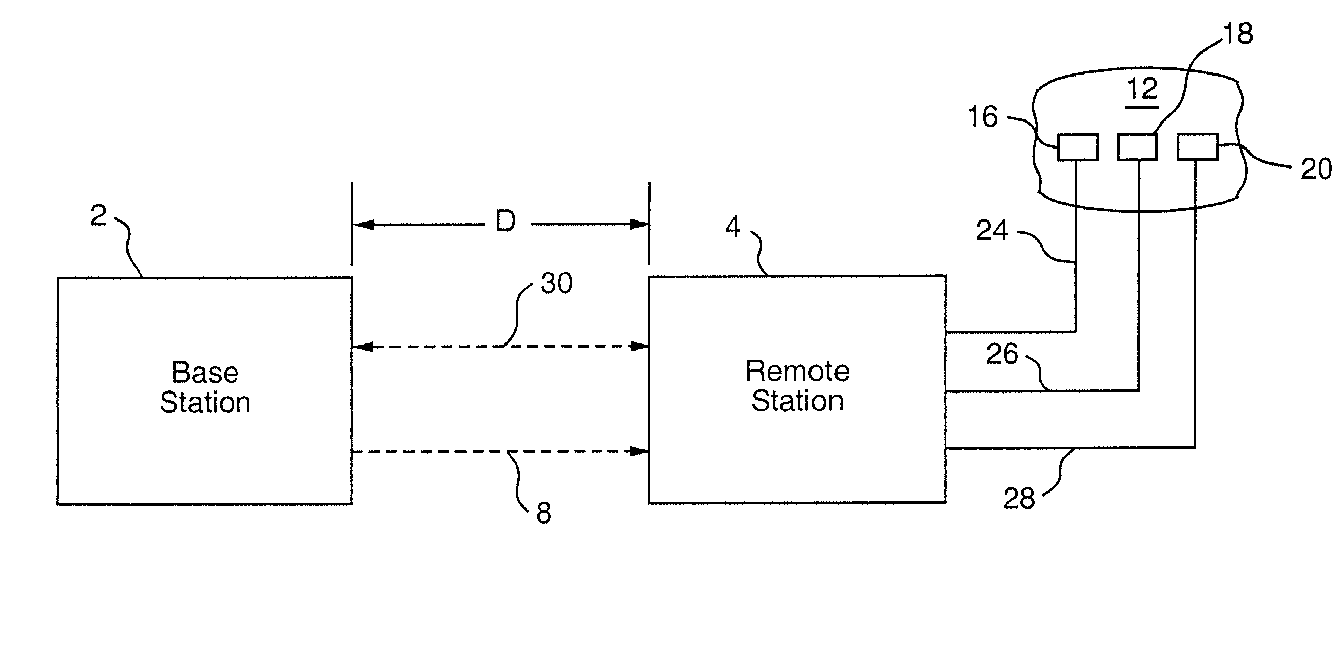
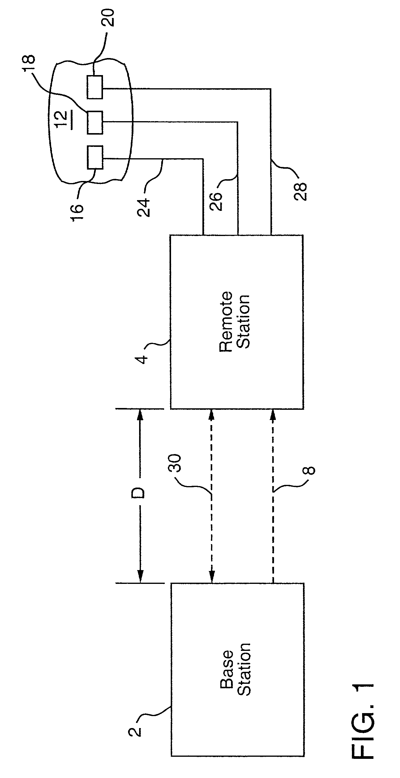
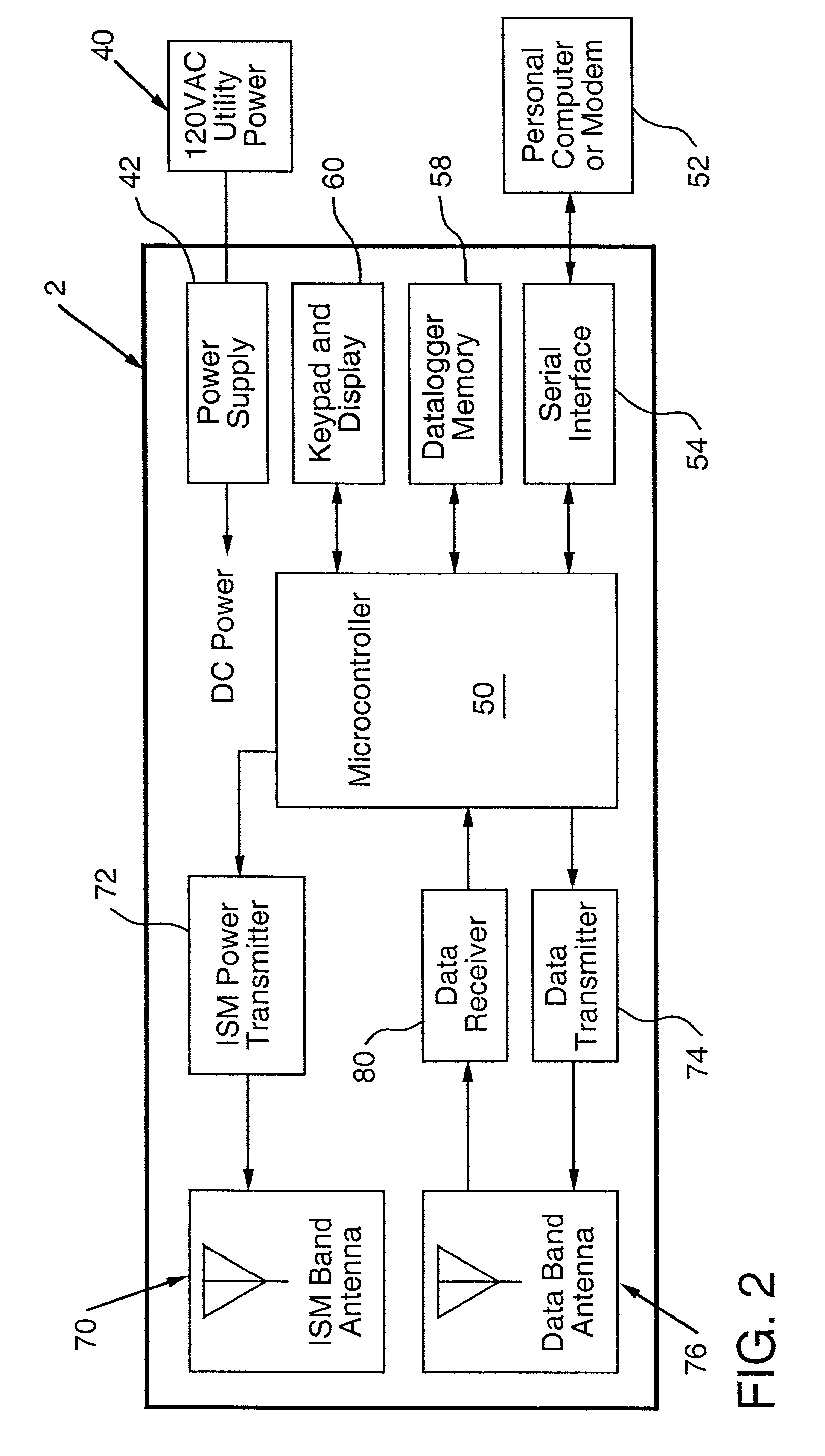
Apparatus for remote interaction with an object of interest includes a remote station for obtaining information from the object of interest, a base station for transmitting energy in space to and communicating with the remote station and the remote station having conversion means for energizing the remote station responsive to receipt of the transmitted energy. The energy may be of any suitable type including RF power, light, acoustic, magnetic energy or other form of space transmitted or "radiant" energy. The remote station does not have to contain a source of stored energy or a wired connection to a source of energy. The remote station receives the energy transmission and data transmission from the base station and transmits data to the base station. Microprocessor controllers may be provided for the base station and the remote station. The remote station may receive information from sensors and through one or more transponders sequentially communicate information to the base station. An associated method is provided. In other embodiments which are suited for use in miniaturized electronic chip systems, power enhancement and increased effective antenna size are provided.

Description

[0001] The present application is a continuation-in-part of U.S. application Ser. No. 09 / 218,322 filed Dec. 22, 1998, now U.S. Pat. No. 6,289,237.[0002] 1. Field of the Invention[0003] This invention relates to apparatus and an associated method for energizing a remote station through energy transmitted in space and, more specifically, it relates to such a system wherein data with respect to an object of interest may be obtained by the remote station and transmitted to the base station upon interrogation by the base station.[0004] 2. Description of the Prior Art[0005] It has long been known in various applications to monitor conditions of a physical system or a patient and provide information in the nature of real-time readouts of certain conditions. Such systems typically have been connected by a suitable wire to a source of electricity at the desired voltage such as line current or batteries.[0006] It has also been known to provide such systems in the medical environment in respec...

Claims


Application Information

Patent Timeline
Patent Type & Authority Applications(United States)
IPC IPC(8): A61B5/00A61B5/04G06K7/00G06K19/07H02J17/00H04Q9/00
CPCA61B5/0031A61B2560/0219G06K7/0008G06K19/0701G06K19/0723G06K19/07775G06K19/07779H02J17/00Y10S128/903A61B5/002H02J50/20H02J50/30H02J50/80H02J2310/23
Inventor MICKLE, MARLINGORODETSKY, DMITRYMATS, LEONIDNEUREUTER, LORENZMI, MINHONGTAYLOR, CARLEMAHIZER, CHAD
Owner PITTSBURGH UNIV OF
Learn More