Optical switching apparatus and method for fabricating

a technology of optical switching and optical waveguide, applied in the direction of optics, optical waveguide light guide, instruments, etc., can solve the problems of high data transmission rate imposing strong requirements on the functionality of switching devices, existing optical switching devices which employ signal conversion from optical into electrical and back into optical do not meet those requirements, and the integration process of such type of switching devices is not robust, reliable, and extendabl

Inactive Publication Date: 2003-02-20
FUJITSU LTD
View PDF3 Cites 26 Cited by
  • Summary
  • Abstract
  • Description
  • Claims
  • Application Information

AI Technical Summary

Problems solved by technology

Furthermore, high data transmission rates impose strong requirements on the functionality of the switching devices.
Existing optical switching devices which employ signal conversion from optical into electrical and back into optical do not satisfy those requirements.
Although, the main principle of the optical cross connect switching based on the light beam deflection is well known, a robust, reliable, low cost and extendable integration process for such type o...

Method used


Image

  • Optical switching apparatus and method for fabricating
  • Optical switching apparatus and method for fabricating
  • Optical switching apparatus and method for fabricating

Examples


Embodiment Construction

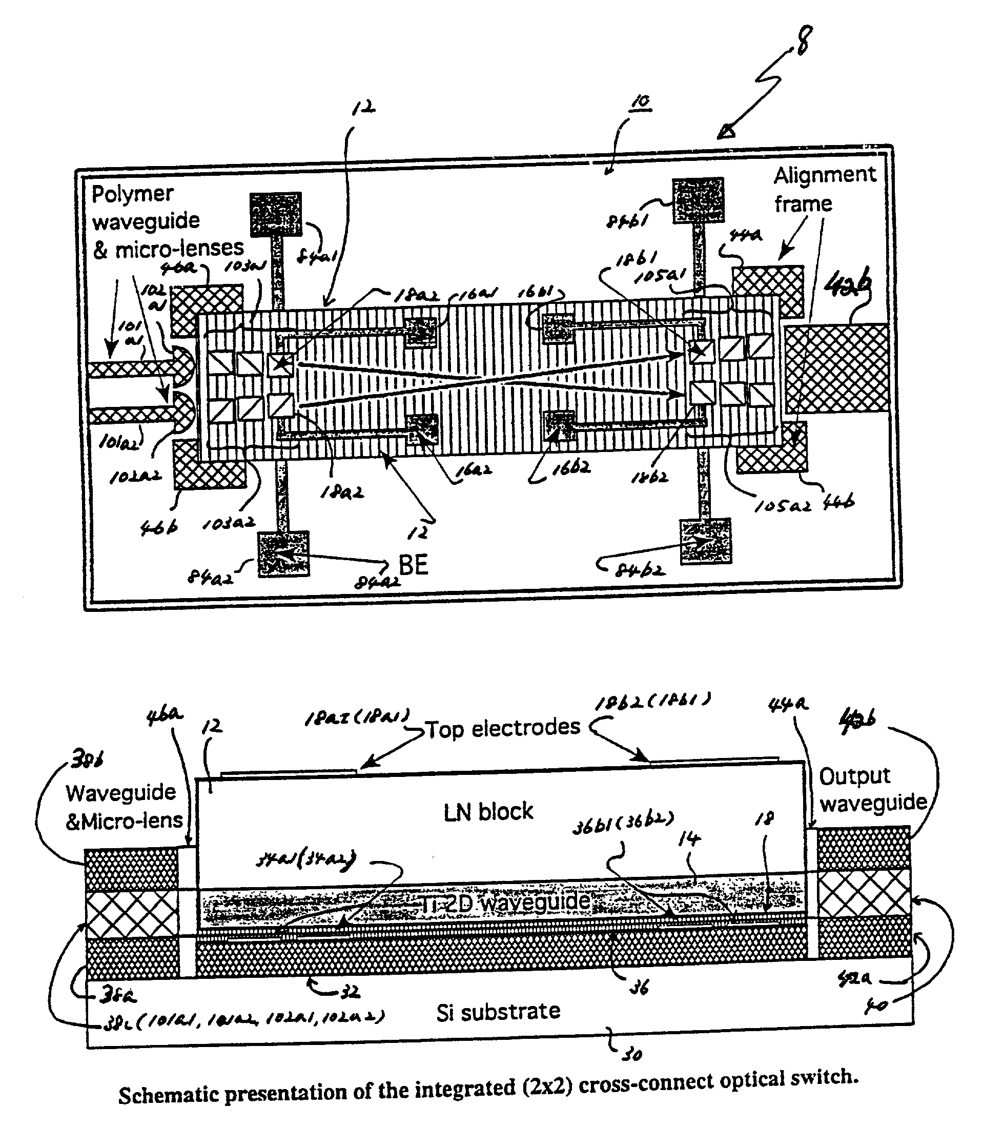
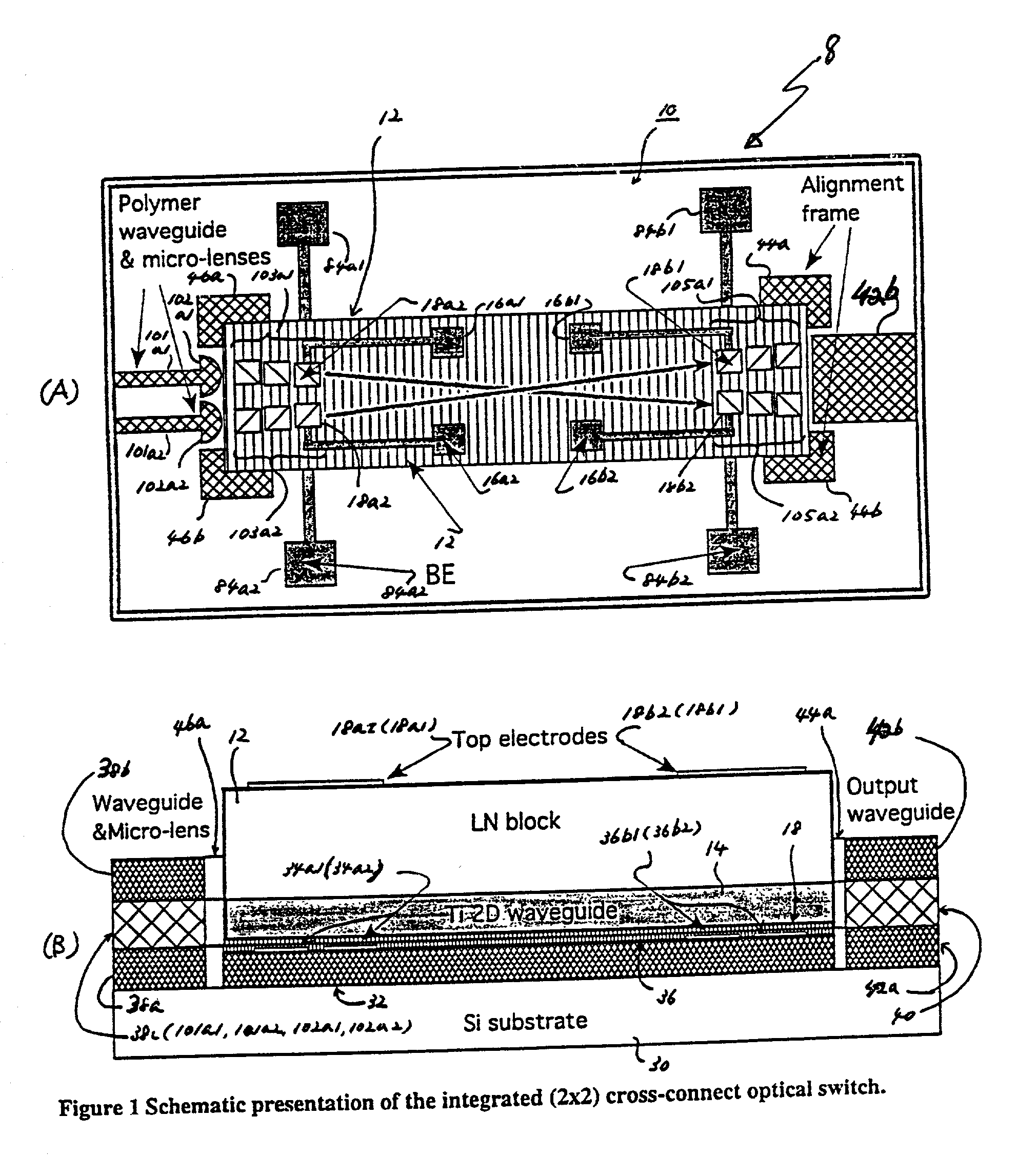
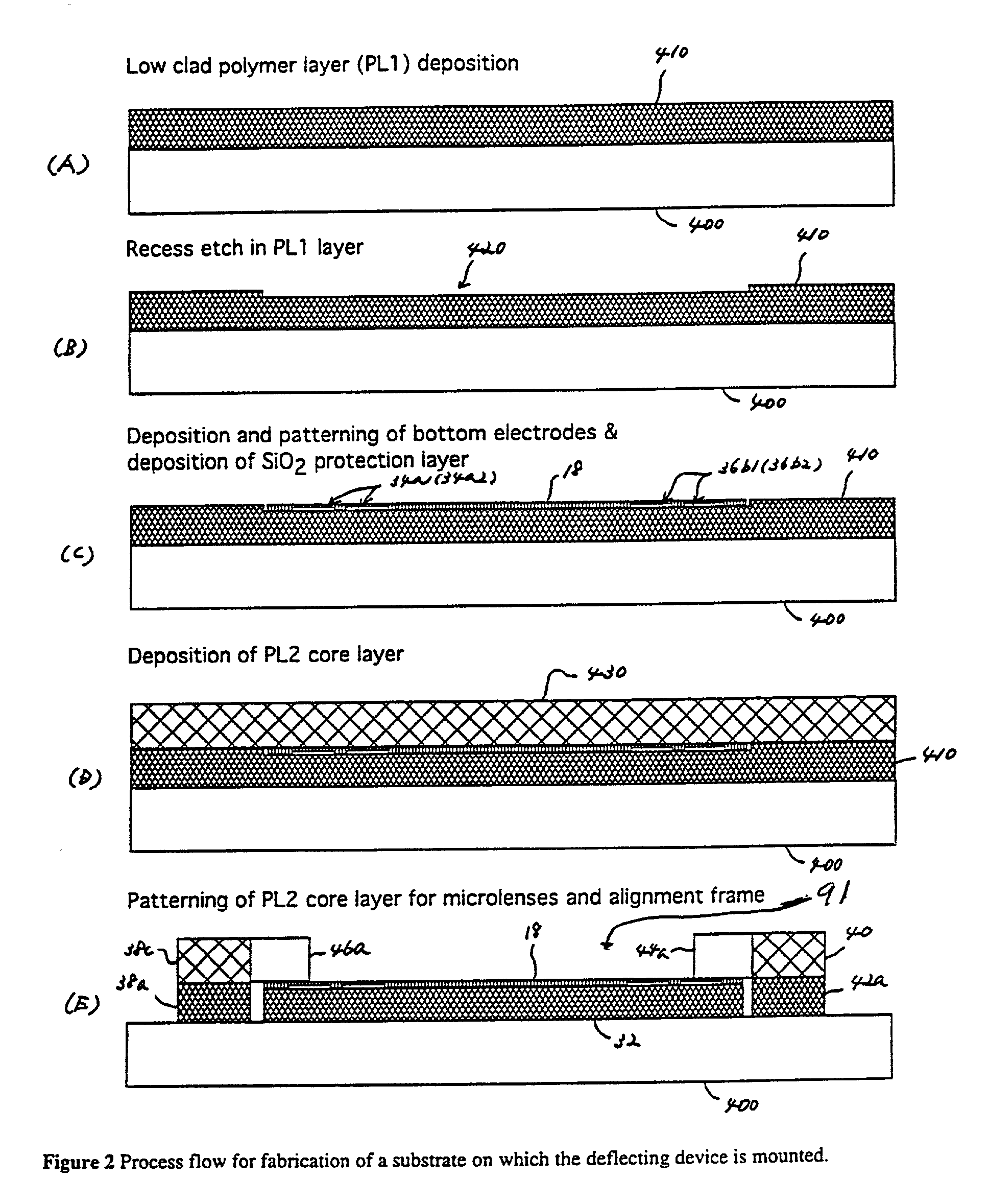
[0031] Referring in detail now to the drawings in combination with the detailed description hereinafter presented, there is illustrated and described an integration process, which allows fabrication of a non-blocking optical cross connect switching matrix with a large (e.g., at least up to 4000) number of I / O channels. The functional principle of the device is based on the EO induced deflection of the incoming optical beam or optical signal that can reroute the incoming light signal from an input port to an output port. Physical principle of the EO induced light beam deflection in piezoelectric materials is well known and is described in an article entitled "Low-Voltage Drive Electro-Optic Pb (Zr, Ti) 0.sub.3 Waveguide Devices Fabricated By Solid-Phase Epitaxy" to Nashimoto et al of the Corporate Research Laboratories of Fuji Xerox Co., Ltd., Japan.

[0032] Embodiments of the present invention provide a hybrid integration process including an OE deflecting element disposed on a silico...


PUM


Abstract

A hybrid integration process for fabrication of an optical cross-connect switching apparatus. The switching element is based on the deflection of light beam in electro-optic materials by applying electric field across electrodes of an appropriate configuration. The integration process includes fabrication of a substrate (e.g. silicon substrate) with 2D imaging optics from polymeric materials (or silica), fabrication of the light deflecting element, and assembly of the deflecting element on the substrate with imaging optics. The fabrication of the light deflecting element includes fabrication of a LN (lithium niobate) block. The LN block assembled in an optical switching apparatus includes a two-dimensional waveguide formed on a surface of the LN block and an electrode on a surface of the LN block.

Description

[0001] 1. Field of the Invention[0002] This invention is related to an optical switching apparatus used in an optical network for voice and data communications. More particularly, embodiments of the present invention provide for an optical switching device and method for fabricating, forming or producing an optical cross-connect switching device.[0003] 2. Description of the Related Art[0004] Strong growth of optical networks for voice and data communication results in huge demand for high data rate information transfer capabilities. To enable such transfer capabilities, dense wavelength division multiplexing (DWDM) technology has been developed which allows transfer of multiple wavelength over the same fiber leading to data transfer rates up to 40-100 Gb / s. High speed switching and routing devices comprise the core elements of the optical networks and allow dynamic control of the data traveling over the optical network. Furthermore, high data transmission rates impose strong require...

Claims


Application Information

Patent Timeline
IPC IPC(8): G02B6/13G02B6/12G02F1/31G02F1/313
CPCG02F1/31
Inventor GLEBOV, ALEXEIPETERS, MICHAELLEE, MICHAELROMAN, JAMESKUDZUMA, DAVID
Owner FUJITSU LTD
Why Eureka
Try Eureka