Electrophoretic display with sub relief structure for high contrast ratio and improved shear and/or compression resistance

a technology of sub relief structure and high contrast ratio, applied in the field of improved electrophoretic display, can solve the problems of poor scratch resistance, difficulties encountered, and own problems

Inactive Publication Date: 2003-03-06
E INK CALIFORNIA
View PDF90 Cites 31 Cited by
  • Summary
  • Abstract
  • Description
  • Claims
  • Application Information

AI Technical Summary

Problems solved by technology

However, each of these has its own problems as noted below.
However, difficulties are encountered in many aspects including the formation of the partitions, the process of filling the display with the fluid, enclosing the fluid in the display and keeping the suspensions of different colors separated from each other.
The large microcapsule size results in a poor scratch resistance and a slow response time for a given voltage because a large gap between the two opposite electrodes is required for large capsules.
Also, the hydrophilic shell of microcapsules prepared in an aqueous solution typically results in sensitivity to high moisture and temperature conditions.
If the microcapsules are embedded in a large quantity of a polymer matrix to obviate these shortcomings, the use of the matrix results in an even slower response time and/or a lower contrast ratio.
However, the microencapsulation process in an a

Method used


Image

  • Electrophoretic display with sub relief structure for high contrast ratio and improved shear and/or compression resistance
  • Electrophoretic display with sub relief structure for high contrast ratio and improved shear and/or compression resistance
  • Electrophoretic display with sub relief structure for high contrast ratio and improved shear and/or compression resistance

Examples


Embodiment Construction

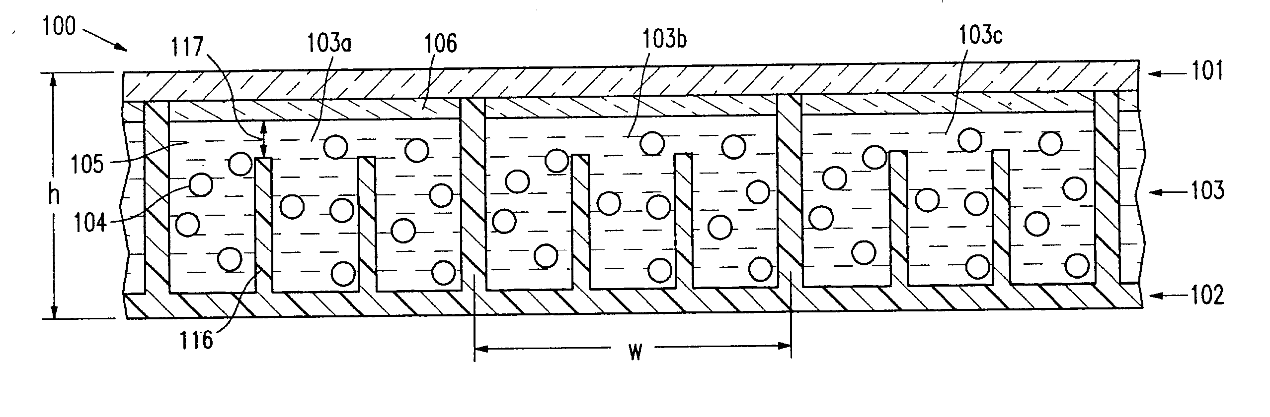
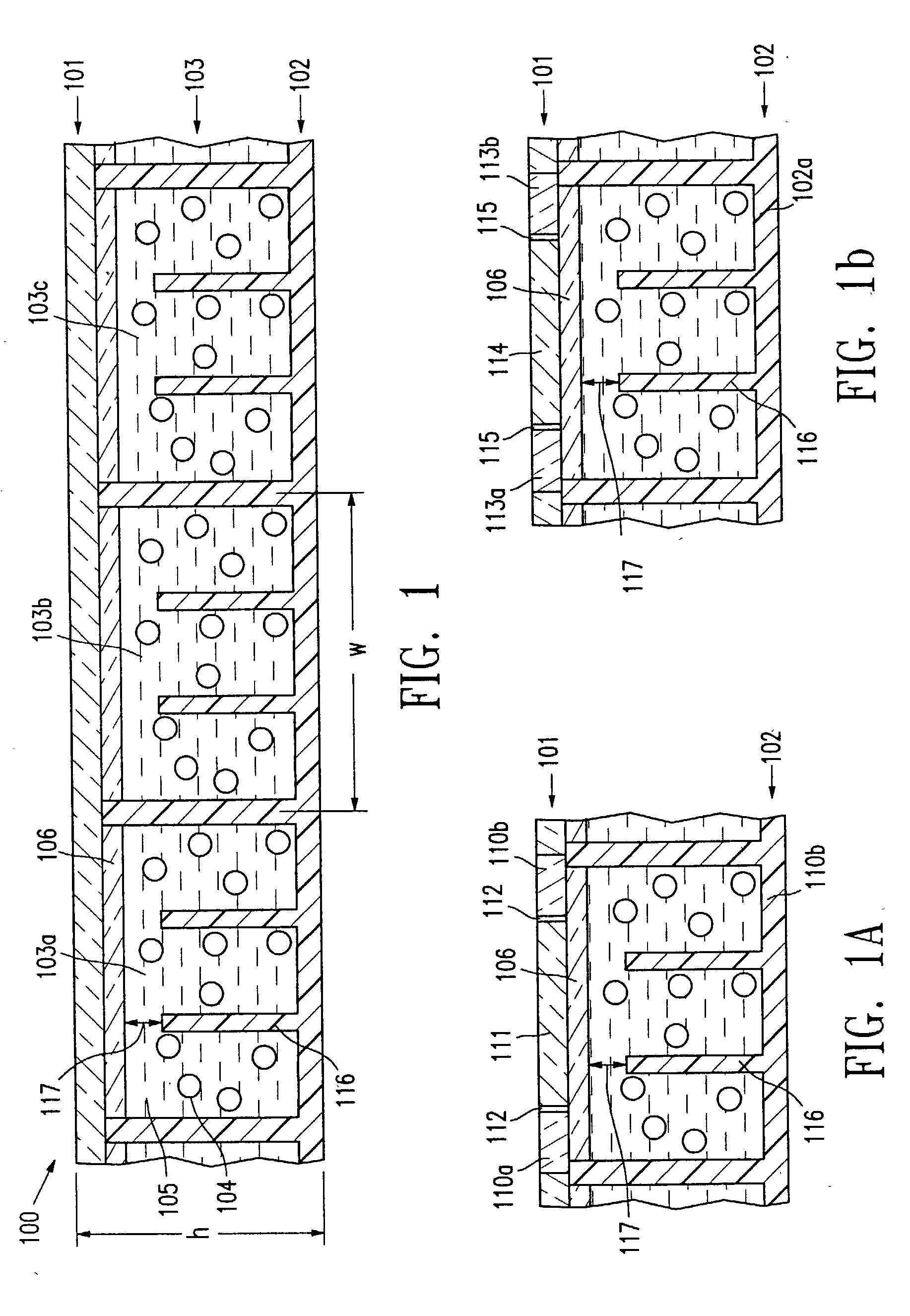
[0031] An electrophoretic display (100) of the present invention, as shown in FIG. 1, comprises a top transparent layer (101), one bottom layer (102) and a layer of isolated cells (103) enclosed between the two layers. The top transparent layer (101) is a transparent conductor film such as ITO on PET. The cells (103a, 103b and 103c) are filled with charged particles (104) dispersed in a dielectric solvent (105) and sealed with a sealing layer (106). The top transparent layer is usually laminated over the sealed cells with an adhesive layer.

[0032] In the display having an in-plane switching mode (FIG. 1a), the bottom layer (102) is an insulator substrate and the top electrode plate (101) comprises in-plane electrodes (110a and 110b) and a top electrode (111) between the two in-plane electrodes separated by gaps (112). Alternatively, the top layer may have only one in-plane switching electrode and one top electrode with a gap in between. In the display having a dual switching mode (FI...


PUM


Abstract

This invention relates to an electrophoretic display comprising isolated cells of well-defined shape, size and aspect ratio which cells have internal sub relief structures and are filled with charged pigment particles dispersed in a dielectric solvent. The display shows an improved contrast ratio and resistance against shear and compression pressures. The display may have the traditional up/down switching mode, an in-plane switching mode or a dual switching mode.

Description

[0001] a) Field of the Invention[0002] This invention relates to an improved electrophoretic display comprising isolated cells of well-defined shape, size and aspect ratio, and the cells have internal sub relief structures and are filled with charged particles dispersed in a dielectric solvent.[0003] The display may have the traditional up / down switching mode, the in-plane switching mode or the dual switching mode.[0004] b) Description of Related Art[0005] The electrophoretic display (EPD) is a non-emissive device based on the electrophoresis phenomenon influencing charged pigment particles suspended in a colored dielectric solvent. This general type of display was first proposed in 1969. An EPD typically comprises a pair of opposed, spaced-apart plate-like electrodes, with spacers predetermining a certain distance between the electrodes. At least one of the electrodes, typically on the viewing side, is transparent. For the passive type of EPDs, row and column electrodes on the top ...

Claims


Application Information

Patent Timeline
IPC IPC(8): G02F1/1343G02F1/167
CPCG02F1/134363G02F1/167
Inventor LIANG, RONG-CHANGHOSSEINI, ABBASCHUANG, HSIAO-KEN
Owner E INK CALIFORNIA
Why Eureka
Try Eureka