Image forming device having paper dust removing units

Inactive Publication Date: 2003-03-13
BROTHER KOGYO KK
View PDF0 Cites 33 Cited by
  • Summary
  • Abstract
  • Description
  • Claims
  • Application Information

AI Technical Summary

Benefits of technology

0009] Therefore, it is an object of the present invention to overcome the above-described drawbacks, and to provide

Problems solved by technology

In the image forming device, paper dusts may be inevitably generated on the sheet due to the friction against the separation pad because each sheet is supplied while being nipped between the sheet supply roller and the separation pad.
However, paper dusts have already inherently existed over the entire surface of the sheet due to sheet cutting.
Therefore, it would be difficult to remove the inherent paper dusts only by such paper dust removing roller having the width the same as that of the separation pad.
However, amount of the paper dust generated by the friction against the separation pad is greater than

Method used


Image

  • Image forming device having paper dust removing units
  • Image forming device having paper dust removing units
  • Image forming device having paper dust removing units

Examples


first embodiment

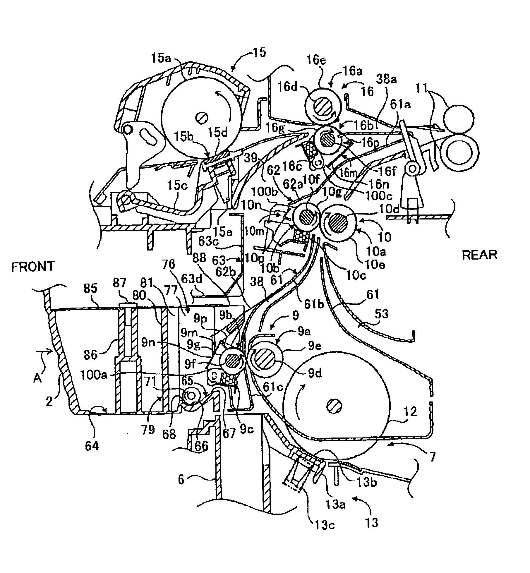
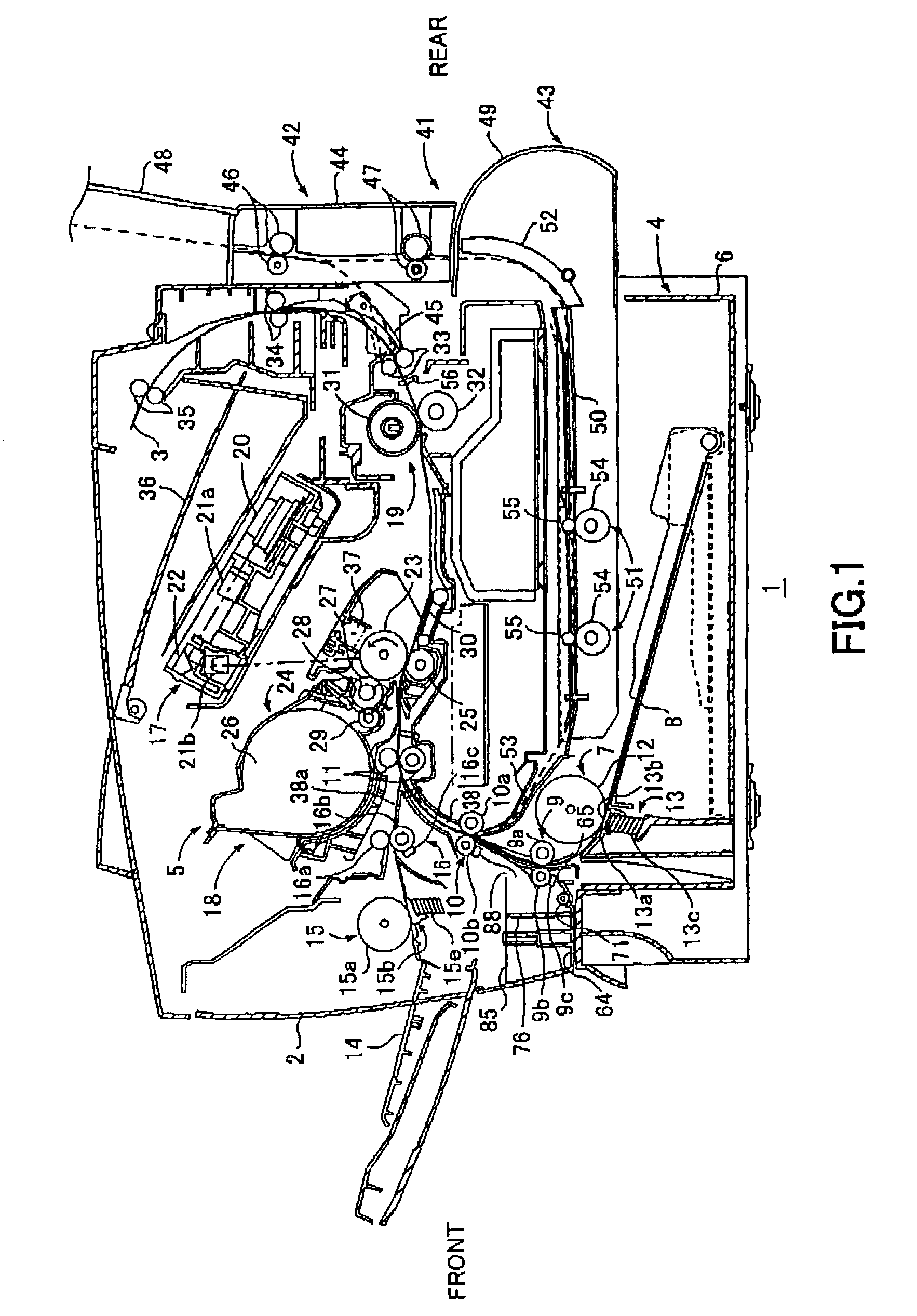
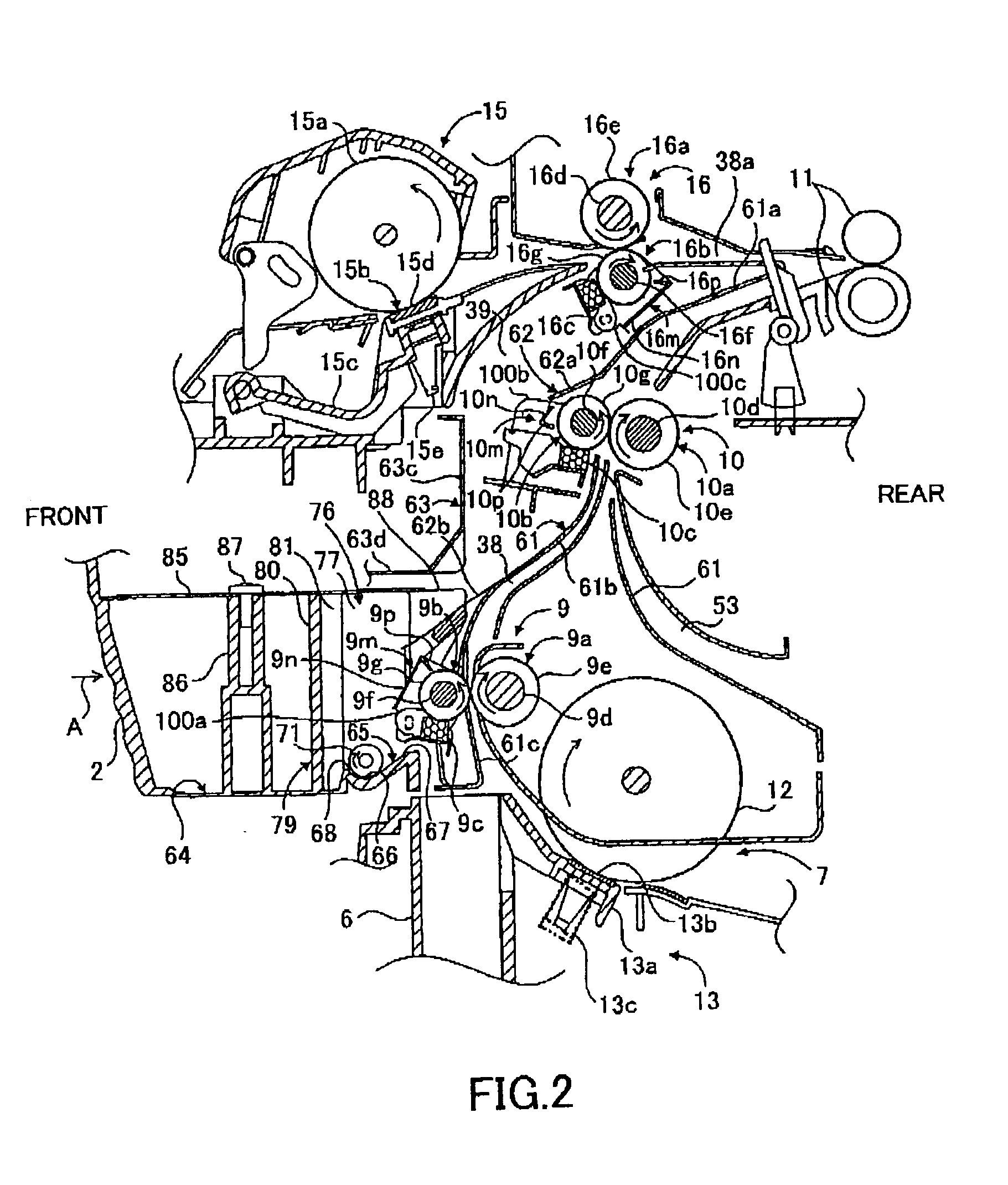
[0037] An image forming device according to the present invention will be described with reference to FIGS. 1 through 8 in which an electro-photographic type laser printer 1 is shown.

[0038] (1) General Arrangement and Image Forming Operation

[0039] As shown in FIG. 1, the printer 1 includes a main casing 2, a feeder portion 4 for feeding a sheet 3 as an image recording medium, and an image forming section 5 for forming an image on the fed sheet 3. The feeder portion 4 and the image forming section 5 are installed in the casing 2.

[0040] The feeder portion 4 includes a sheet supply tray 6 positioned on a bottom of the main casing 2 and detachable therefrom, a sheet supply section 7 disposed at one side of the sheet supply tray 6, a sheet mount plate 8 disposed in the sheet supply tray 6, a first transport portion 9 (a first paper dust removing unit), a second transport portions 10 (a second paper dust removing unit), and a register roller 11. The first and second transport portions 9 a...

second embodiment

[0169] (5) Second Embodiment

[0170] An image forming device according to a second embodiment of the present invention will be described with reference to FIGS. 9 through 13(b) wherein like parts and components are designated by the same reference numerals and characters as those shown in the first embodiment shown in FIGS. 1 through 8. A laser printer 101 according to the second embodiment is different from the first embodiment in terms of the arrangement of collection of paper dusts.

[0171] In a second transport portion 110, a second paper dust removing roller 110b is driven upon power input from a motor (not shown) into an input gear 110h as shown in FIG. 10, serving as power input means mounted on one end portion of the roller shaft 110f, so that the second paper dust removing roller 110b is rotatable in a direction indicated by an arrow in FIG. 9, that is, in the sheet feeding direction (counter clockwise direction in FIG. 9) at a region facing with the sheet transport path 38. Th...


PUM

PropertyMeasurementUnit
Lengthaaaaaaaaaa
Angleaaaaaaaaaa
Forceaaaaaaaaaa

Abstract

An image forming device capable of sufficiently removing paper dusts on a sheet thereby providing high quality image. A sheet transport path 38 is defined between a sheet supply section 7 provided with a separation pad 13 and a sheet supply roller 12 and an image forming section 5. Along the sheet supply section 7, at least a first paper dust removing roller 9b having a width slightly greater than the width of the separation pad 13 and a second paper dust removing roller 10b having a width slightly greater than the sheet width are disposed. Paper dusts generated upon friction against the separation pad 13 are removed by the first paper dust removing roller 9b, and paper dusts spreading over entire surface of the sheet are removed by the second paper dust removing roller 10b.

Description

CROSS REFERENCE TO RELATED APPLICATION[0001] This is a Continuation-in-Part of application Ser. No. 09 / 852,746 filed May 11, 2001, which in turn is a Continuation-in-Part of application Ser. No. 09 / 817,170 filed Mar. 27, 2001 and a Continuation-in Part of application Ser. No. 09 / 824,054 filed Apr. 3, 2001 now abandoned, which in turn is a Divisional application of Ser. No. 09 / 409,386 filed Sep. 30, 1999, now patented as U.S. Pat. No. 6,219,505BACKGROUND OF THE INVENTION[0002] The present invention relates to an image forming device such as a laser printer.[0003] An image forming device such as a laser printer generally includes a sheet supply section for supplying sheets and an image forming section for forming an image on a sheet supplied from the sheet supply section. The sheet supply section generally includes a sheet supply tray on which a stack of sheets is mounted, a sheet supply roller positioned near one end and above the sheet supply tray, and a separation pad positioned in...

Claims


Application Information

Patent Timeline
IPC IPC(8): B41J13/02B65H5/06B65H37/00G03G15/00G03G21/00G03G21/18
CPCB41J13/02B65H5/06B65H37/00B65H2301/531B65H2301/532G03G15/6558G03G15/235G03G2215/00607G03G2215/00708G03G2221/0042G03G2221/0068G03G15/1665G03G21/0064
Inventor FUWAZAKI, TAKESHIHATTORI, MAKOTOFUKUTA, KAZUSHI
Owner BROTHER KOGYO KK
Why Eureka
Try Eureka