Device and method for detecting a misfire state of an engine

Inactive Publication Date: 2003-03-20
TOYOTA JIDOSHA KK
View PDF1 Cites 11 Cited by
  • Summary
  • Abstract
  • Description
  • Claims
  • Application Information

AI Technical Summary

Benefits of technology

[0013] It is a second object of this invention to provide a method which permits accurate detection of a misfire of the engine, even where such starting of the engine is repeated.
[0016] In the misfire detecting device and method according to the present invention described above, the memory area of the memory which stores the misfire-frequency data relating to the frequency of occurrence of the misfire of the engine is cleared when the controller determines that the engine has failed to entered into its firing state by cranking of the engine for starting thereof. That is, the memory area is cleared before the engine is cranked again for starting of the engine after a firing failure of the engine by the last cranking operation. Thus, the present misfire detecting device and method are arranged to prevent a change of the misfire-frequency data stored in the memory, where cranking operations of the engine are repeated due to repeated firing failures of the engine. Accordingly, the present device and method permit accurate detection of a misfiring state of the engine, irrespective of such repeated firing failures. The predetermined first and second conditions may be the same condition. In this case, the controller determines that the engine has entered into its firing state, when the condition is satisfied, and determines that the engine has failed to enter into its firing state, when the condition is not satisfied.
[0019] In the misfire detecting device and method according to the above-indicated further aspects of the present invention, the memory area of the memory which stores the misfire-frequency data relating to the frequency of occurrence of the misfire of the engine is cleared before a cranking operation of the engine for starting thereof is repeated after a firing failure of the engine by the last cranking operation. Thus, the misfire detecting device and method described above are arranged to prevent a change of the misfire-frequency data stored in the memory, where cranking operations of the engine are repeated due to repeated firing failures of the engine. Accordingly, the present device and method permit accurate detection of a misfiring state of the engine, irrespective of such repeated firing failures.

Problems solved by technology

An engine may suffer from a "misfire", which is an incomplete combustion of an air-fuel mixture in a combustion chamber that takes place under certain conditions such as an operating temperature of the engine and a state of a spark plug.
When a misfire takes place in the combustion chamber, not only the operating speed of the engine drops, but also incomplete combustion gases are exhausted from the combustion chamber into the atmosphere.
Frequent occurrence of the misfire disables the engine to produce its nominal torque.
Namely, an occurrence of a misfire in a given cylinder causes a drop of the operating speed of the engine in the combustion cycle involving the misfiring cylinder.
If the frequency of occurrence of the misfire has exceeded the threshold, it is detected that the engine is suffering from the misfire.
However, a variation of the operating speed of the engine does not take place solely due to a misfire in the combustion chambers of the engine.
It may occur that a detection of a misfire of the combustion engine is not normally performed, due to the variation of the operating of the operating speed of the engine, caused by the above-described abrupt brake or running on a rough road.
However, it is difficult to accurately detect the moment of transition of the engine to its firing state.
This difference may cause the following problems.
If the engine starting that does not result in the firing state of the engine is repeated, the frequency of occurrence of the misfire as represented by the stored misfire-frequency data is increased, leading to a risk that the ECU erroneously determines that the engine is in the misfiring state, while in fact the engine has not entered into the firing state.

Method used


Image

  • Device and method for detecting a misfire state of an engine
  • Device and method for detecting a misfire state of an engine
  • Device and method for detecting a misfire state of an engine

Examples


Embodiment Construction

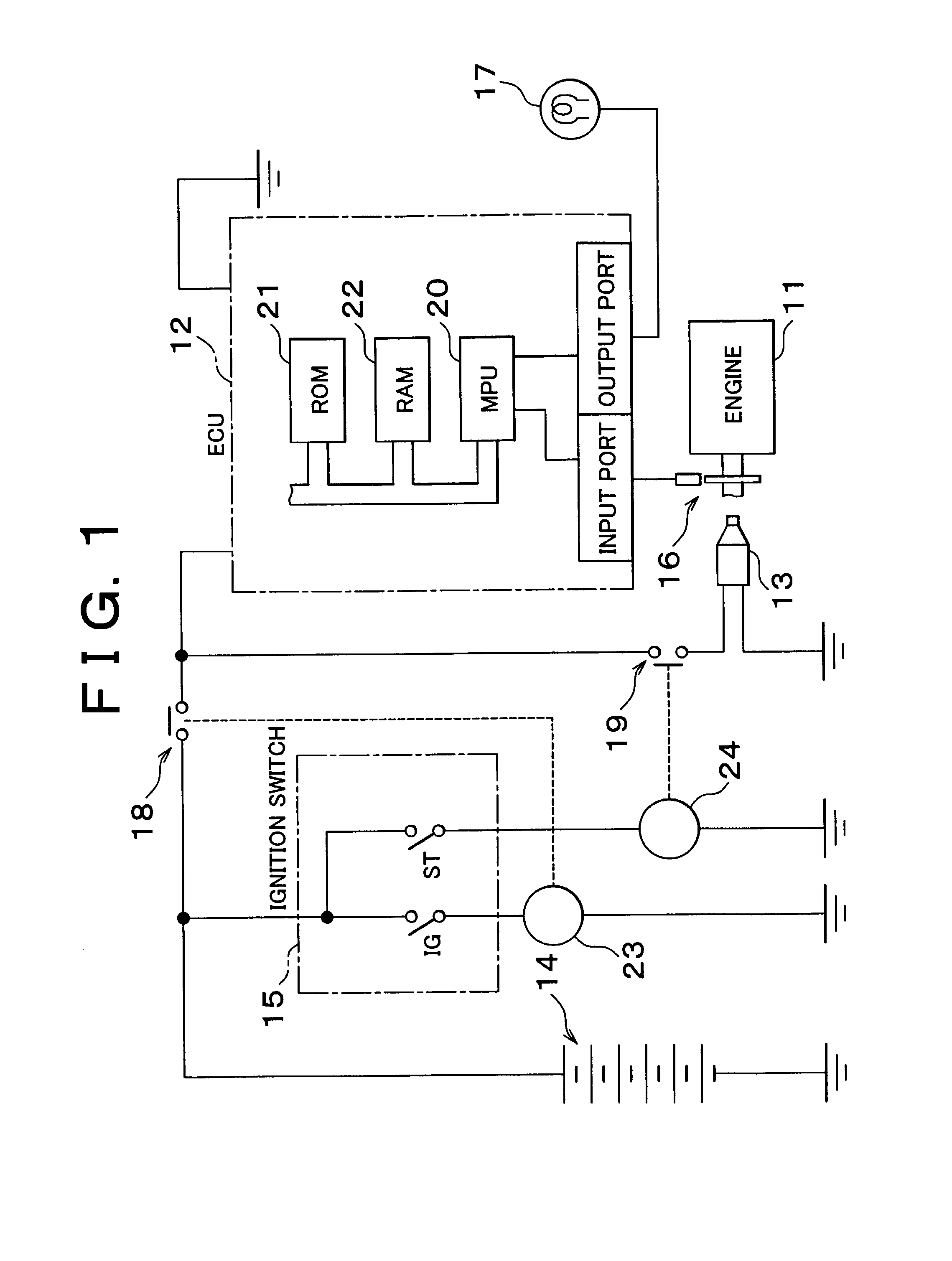
[0025] FIG. 1 illustrates a control apparatus for an engine 11 (hereinafter referred to as "engine 11") for an automotive vehicle. This control apparatus incorporates a misfire detecting device according to one exemplary embodiment of the present invention, and includes an electronic control unit (ECU) 12, a starter 13 for starting the engine 11, a battery 14 serving as an electric power source for the ECU 12 and the starter 13, and an ignition switch 15 for connecting the ECU 12 and the starter 13 to the battery 14. The engine 11 is provided with a crank angle sensor 16 for detecting an angular phase or position of its output shaft in the form of a crankshaft. The crank angle sensor 16 generates an output signal indicative of the angular position of the crankshaft, which is applied to an input port of the ECU 12. The output signal of the crank angle sensor 16 received by the input port is used not only for detecting not only the angular phase or angular position of the crankshaft, ...


PUM


Abstract

A misfire detecting device and method detects a misfiring state of an engine. A memory stores misfire-frequency data relating to a frequency of occurrence of a misfire of the engine, and a controller determines, on the basis of the misfire-frequency data, whether the misfiring state of the engine has occurred. The controller initiates a misfire detecting operation of detecting an occurrence of the misfire of the engine when a predetermined first condition is satisfied, and initializes the misfire-frequency data stored in the memory when a predetermined second condition is satisfied. The first condition indicates that the engine has entered into its firing state by cranking of the engine for starting thereof, while the second condition indicates that the engine has failed to enter into its firing state by the cranking. The misfire detecting device permits accurate detection of the misfiring state of the engine, irrespective of repeated cranking operations of the engine due to its repeated firing failures.

Description

INCORPORATION BY REFERENCE[0001] The disclosure of Japanese Patent Application No. 2001-252828 filed on Aug. 23, 2001, including the specification, drawings and abstract, is incorporated herein by reference in its entirety.[0002] 1. Field of Invention[0003] The present invention relates to a device for detecting a misfiring state of an engine, and a method of detecting the misfire.[0004] 2. Description of Related Art[0005] An engine may suffer from a "misfire", which is an incomplete combustion of an air-fuel mixture in a combustion chamber that takes place under certain conditions such as an operating temperature of the engine and a state of a spark plug. When a misfire takes place in the combustion chamber, not only the operating speed of the engine drops, but also incomplete combustion gases are exhausted from the combustion chamber into the atmosphere. Frequent occurrence of the misfire disables the engine to produce its nominal torque. Further, it is desired to reduce the amoun...

Claims


Application Information

Patent Timeline
IPC IPC(8): F02D45/00G01M15/11
CPCG01M15/11
Inventor HASHIGUCHI, YUKIHIDE
Owner TOYOTA JIDOSHA KK
Why Eureka
Try Eureka