Ophthalmic instrument having hartmann wavefront sensor with extended source

a wavefront sensor and ophthalmology technology, applied in the field of ophthalmology instruments, can solve the problems of inability to measure and characterize the higher order refractive error, and inability to compensate the aberrations of the ey

Inactive Publication Date: 2003-03-20
ADAPTIVE OPTICS ASSOC
View PDF0 Cites 80 Cited by
  • Summary
  • Abstract
  • Description
  • Claims
  • Application Information

AI Technical Summary

Problems solved by technology

Conventional phoropters and autorefractors characterize the refractive errors of the eye only in terms of focal power (typically measured in diopter) required to compensate for such focal errors; thus, such instruments are incapable of measuring and characterizing the higher order aberrations of the eye, including astigmatism and spherical aberration.
This refractive error is reported to the user of the apparatus through an attached LCD.
Notably, the apparatus of Fahrenkrug et al. does not provide for compensation of the aberrations of the eye.
Moreover, the apparatus of Fahrenkrug et al. and the apparatus of Williams and Liang do not provide a view of the compensation of the aberrations to the eye.
Thus, the patient cannot provide immediate feedback as to the accuracy of the measurement; and must wait until compensating optics (such as a contact lens or glasses that compensate for the measured aberrations) are provided in order to provide feedback as to the accuracy of the measurement.
This may lead to repeat visits, thereby adding significant costs and inefficiencies to the diagnosis and treatment of the patient.
In addition, the wavefront sensing apparatus (i.e., the lenslet array and imaging sensor) of Fahrenkrug et al. and of Williams and Liang are susceptible to a dot crossover problem.
Such overlap (or crossover) introduces an ambiguity in

Method used


Image

  • Ophthalmic instrument having hartmann wavefront sensor with extended source
  • Ophthalmic instrument having hartmann wavefront sensor with extended source
  • Ophthalmic instrument having hartmann wavefront sensor with extended source

Examples


Embodiment Construction

[0072] Referring to the figures in the accompanying Drawings, the preferred embodiments of the ophthalmic instruments of the present invention will be described in greater detail, wherein like elements will be indicated using like reference numerals.

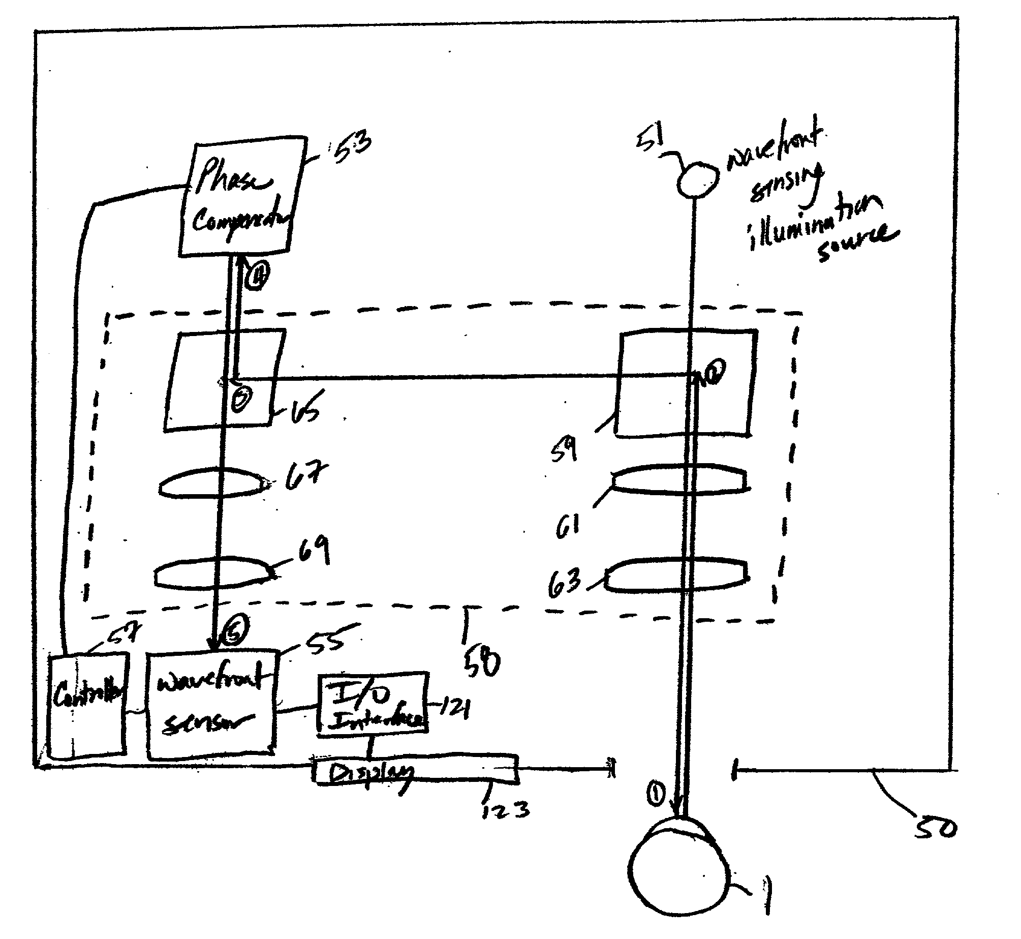
[0073] According to the present invention, an ophthalmic instrument includes an adaptive optic subsystem that forms an image of a wavefront sensing illumination source on the retina of the eye under examination, which is reflected (thereby exiting the pupil of the eye as distorted wavefronts) and directed back to the instrument. An image of the reflected wavefronts (which represent retroreflection of the image formed on the retina and exit the pupil of the eye as distorted wavefronts) is created on a phase compensator (which preferably comprises a variable focus lens and a deformable mirror) and recreated at a wavefront sensor. The phase compensator operates to spatially modulate the phase of the image of the distorted wavefronts inciden...


PUM

PropertyMeasurementUnit
Sizeaaaaaaaaaa
Dimensionaaaaaaaaaa
Correlation functionaaaaaaaaaa

Abstract

An improved ophthalmic instrument including an extended source producing light that is formed as an image on the retina of the human eye and reflected there from to produce retinal reflections derived from the extended source, and a wavefront sensor that estimates aberrations in the retinal reflections. The wavefront sensor includes a plurality of subapertures that form a plurality of images of the extended source from the retinal reflections, an imaging device that captures the plurality of images and outputs image data representing the images, and an image processing computer that generates an estimate of the gradient field of the retinal reflections by applying image correlation techniques in the digital domain to the image data. The image processing computer preferably generates an estimate of the local tilt of the retinal reflections incident on a given subaperture by deriving a correlation product for a given image formed by the given subaperture and identifying a peak correlation point of the correlation product. The dimensions of the image of the extended source formed on the retina of the human eye is preferably larger that a diffraction limited spot yet small enough so that different parts of the image do not experience substantially different aberrations while passing through the eye. In addition, the angular size of the image of the extended source is preferably limited so that the plurality of images formed by the subapertures do not overlap.

Description

[0001] The present Application is related to the following U.S. patent applications: copending application Ser. No. ______ (Attorney Docket No. 108-109USA000), filed concurrently herewith, entitled "Ophthalmic Instrument With Adaptive Optic Subsystem That Measures Aberrations (Including Higher Order Aberrations) Of A Human Eye And That Provides A View Of Compensation Of Such Aberrations To The Human Eye," by Bruce M. Levine, Allan Wirth, and C. Harry Knowles; copending application Ser. No. ______ (Attorney Docket No. 108-129USA000), filed concurrently herewith, entitled "Ophthalmic Instrument Having Adaptive Optic Subsystem With Multiple Stage Phase Compensator," by Bruce M. Levine; copending application Ser. No. ______ (Attorney Docket No. 108-130USA000), filed concurrently herewith, entitled "Ophthalmic Instrument Having Wavefront Sensor With Multiple Imaging Devices that Simultaneously Capture Multiple Images Of An Array Of Spots Produced By A Lenslet Array," by Allan Wirth; cope...

Claims


Application Information

Patent Timeline
IPC IPC(8): A61L27/00A61B3/103A61F2/02A61L31/04
CPCA61L31/048A61B3/103A61B3/1015C08L27/16
Inventor WIRTH, ALLAN
Owner ADAPTIVE OPTICS ASSOC
Why Eureka
Try Eureka