Ultrasonic probe

a technology of ultrasonic probes and probes, applied in the field of ultrasonic probes, can solve the problems of reducing the resolution of ultrasonic images, affecting the accuracy of ultrasonic images, and not always being able to match the specific acoustic impedance, so as to prevent the total internal reflection

Inactive Publication Date: 2003-03-27
ALOKA CO LTD
View PDF0 Cites 12 Cited by
  • Summary
  • Abstract
  • Description
  • Claims
  • Application Information

AI Technical Summary

Benefits of technology

0044] Under the above condition, C.sub.2<C.sub.1, when an ultrasonic wave is incident from the first member into the second member, no total internal reflection of the ultrasonic wave is generated regardless of the size of .theta., in accordance to Snell's law. In contrast, when an ultrasonic wave is incident from the second member, in which the sonic speed is smaller, to the first member, in which the sonic speed is larger, whether or not a total internal reflection is generated at the boundary depends on the incident angle of the ultrasonic wave with respect to the boundary. Here, the direction of the actual propagation of the ultrasonic waves is primarily in the direction of normal with respect to the surface of the acoustic match

Problems solved by technology

However, with the ultrasonic probe according to the above related art, because the specific acoustic impedances of the sonic speed control elements change dynamically, the specific acoustic impedance tends to not match at the boundary between a sonic speed control element and an acoustic matching layer, boundary between two adjacent acoustic matching layers, and boundary between an acoustic matching layer and the living body.
As a result, lingering (

Method used


Image

  • Ultrasonic probe
  • Ultrasonic probe
  • Ultrasonic probe

Examples


Embodiment Construction

[0075] The preferred embodiments of the present invention will now be described with reference to the drawings.

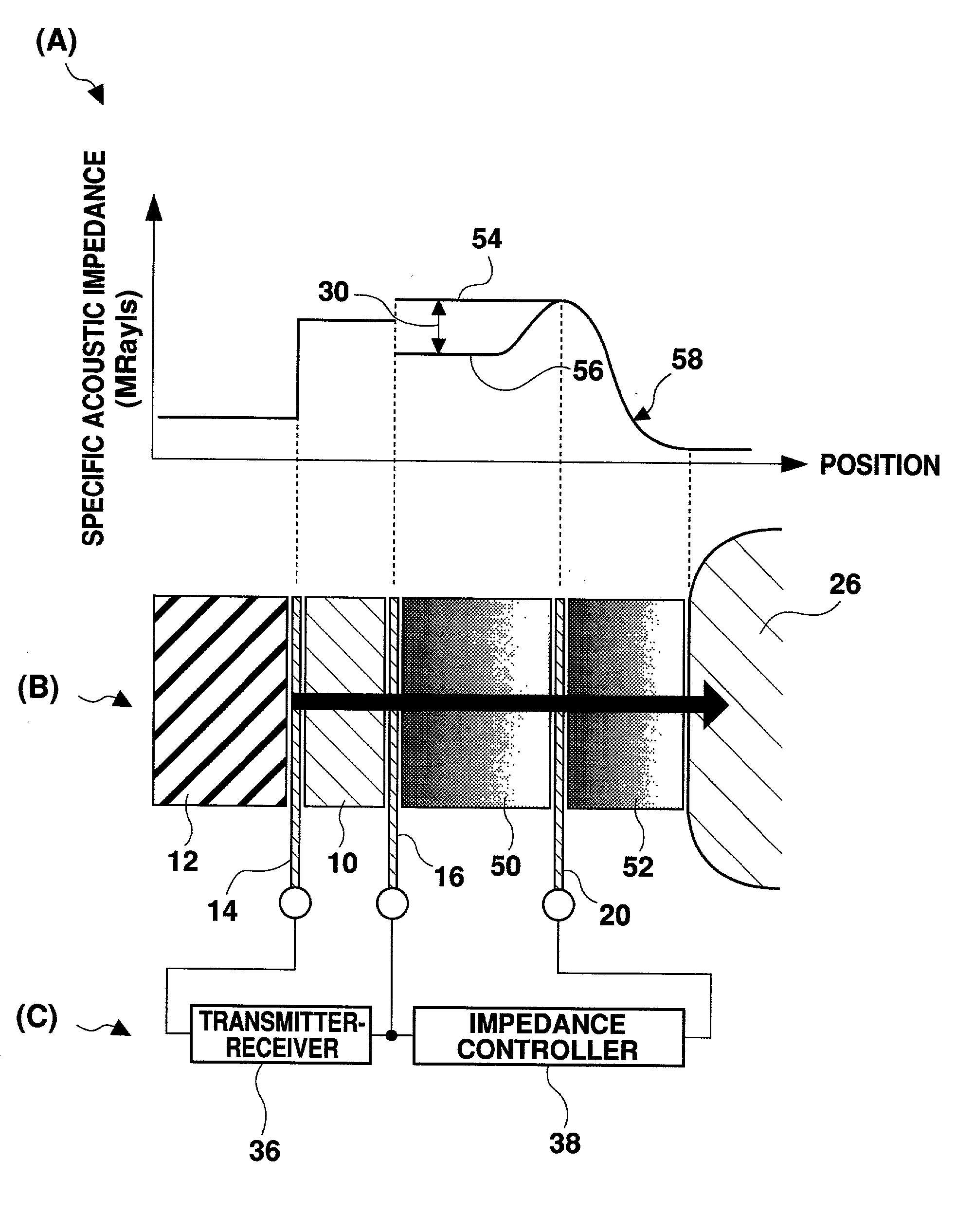
[0076] FIG. 1 shows the principle of an ultrasonic probe according to the present invention. An ultrasonic probe in this embodiment comprises an array transducer as shown in FIG. 7. FIG. 1 shows one of the transducer elements 10 of the array transducer along with other structures. FIG. 1(B) is a cross sectional view of a portion of the ultrasonic probe, FIG. 1(A) shows the variation in the specific acoustic impedance along the direction of travel of the ultrasonic waves (thickness direction), and FIG. 1(C) shows a plurality of electrical circuits.

[0077] As shown in FIG. 1(B), the transducer element 10 is for transmitting / receiving ultrasonic waves. The transducer element 10 is made of, for example, a PZT or composite piezoelectric material. At the side of the transducer element 10 away from the living body, a backing layer 12 is abutted with a signal lead 14 in between. The...


PUM


Abstract

An ultrasonic probe which is used for ultrasonic diagnosis comprises a transducer element, a sonic speed control element, and an acoustic matching layer. The sonic speed control element has a function to control the sonic speed of the ultrasonic waves traveling therethrough, and has an inclined characteristic in the sonic speed control effect in which the sonic speed control effect changes continuously along the direction of travel of the ultrasonic waves (thickness direction). The specific acoustic impedance of the sonic speed control element at the end near the living body corresponds to the specific acoustic impedance of the acoustic matching layer at the end away from the living body. The acoustic matching layer is preferably formed by layering 2 or 3 or more overlapped members. The boundary between two adjacent members has a shape with a plurality of hills and valleys. The crossing angle between the direction of travel of the ultrasonic waves and the boundary is set so that a predetermined condition is satisfied.

Description

[0001] 1. Field of the Invention[0002] The present invention relates to an ultrasonic probe and, more particularly, to an ultrasonic probe having a sonic speed control element.[0003] 2. Description of the Related Art[0004] In ultrasonic diagnosis, in general, an ultrasonic probe is brought into contact with a surface of a living body and an ultrasonic wave is transmitted and / or received in that state. Japanese Patent Laid-Open Publication No. Hei 11-123188 discloses a new type of an ultrasonic probe which has a sonic speed control element. In this ultrasonic probe, a sonic speed control element is provided on the upper surface of a transducer for transmission / reception of ultrasonic waves. On the upper surface of the sonic speed control element, one or two acoustic matching layers are provided.[0005] Similar to the transducer, a sonic speed control element is formed from, for example, a piezoelectric material. An external circuit is connected to the sonic speed control element. When...

Claims


Application Information

Patent Timeline
IPC IPC(8): G10K11/02H04R1/34A61B8/00H04R17/00
CPCG10K11/02A61B8/4494
Inventor SATO, SHOHEI
Owner ALOKA CO LTD
Why Eureka
Try Eureka