Dustfree filling and sealing apparatus, dustfree container and wrapping clean film producing method

a filling and sealing apparatus and a technology for cleaning film, applied in the direction of film/foil adhesives, packaging, synthetic resin layered products, etc., can solve the problems of increasing wrapping costs and complicated apparatus construction, and achieve the effects of less penetration of vapor, less moisture absorption, and low density

Inactive Publication Date: 2003-04-03
DAI NIPPON PRINTING CO LTD
View PDF21 Cites 30 Cited by
  • Summary
  • Abstract
  • Description
  • Claims
  • Application Information

AI Technical Summary

Benefits of technology

0066] As described above, according to the first embodiment of the present invention, since the wrapping clean film where the clean surfaces of the inner layer film appear by peeling off the outer layer films is used, it is not necessary to clean the wrapping clean film with ultrapure water. Thus, a wrapping material cleaning facility is not required. In addition, an object can be securely wrapped free of dust.
0069] Next, a clean film producing method according to a second embodiment of the present invention will be described. A resin which forms an inner layer film and another resin which forms outer layer films which is applied to the inner layer film for peelably coating the front and rear surfaces of the inner layer film are co-extruded in a molten state from an extruder by for example T-die method. Thus, as shown in FIG. 4, one inner layer film 21 and two outer layer films 2 are laminated.
0070] The co-extruding temperature is 230.degree. C. or below, preferably 220.degree. C. or below. This is because when the co-extruding temperature exceeds 230.degree. C., the peeling property of the outer layer films 22 to coat the front and rear surfaces of the inner layer film 21 may deteriorate.
0071] The inner layer film 21 is used for a wrapping material which is directly in contact with an object such as a semiconductor product. When the wrapping clean film used, the outer layer films 22 to coat both the front and rear surfaces of the inner layer film 21 are peeled off therefrom. Since the inner layer film 21 and the two outer layer films 22 are laminated by co-extrusion method, the front and rear surfaces of the inner layer film 21 are not directly exposed to outer air while and after the wrapping clean film is produced. Thus, dirt and dust never adhere to the front and rear surfaces of the inner layer film 21 after the wrapping clean film is produce and until it is used.
0072] An example of the material of the inner layer film 21 is low density polyethylene (LDPE) with a density in a range from 0.900 to 0.960 g / cm.sup.3, preferably in a range from 0.915 to 0.930 g / cm.sup.3. This is because the low density polyethylene (LDPE) less penetrates vapor, less absorbs moisture, and is inexpensive. When the density of the low density polyethylene is less than 0.900 g / cm.sup.3, a blocking may take place, thereby deteriorating the peeling property against the outer layer films 22. On the other hand, when the density of the low density polyethylene exceeds 0.960, the inner layer film 21 may become weak and thereby easily breakable.
0074] The outer layer films 22 to coat the front and rear surfaces of the inner layer film 21 prevent dirt and dust from adhering to the front and rear surfaces thereof. In addition, the outer layer films 22 can be easily peeled off and removed from the inner layer film 21. Thus, as shown in FIG. 5, when the inner layer film 21 is used, by peeling off and removing the outer layer films 22, clean surfaces of the inner layer film 21 appear because the outer layer films 22 prevent dirt and dust from adhering to the front and rear surfaces of the inner layer film 21.

Problems solved by technology

Since semiconductor products such as IC chips and LSI chips are much delicately and adversely affected by dirt and dust, they are produced in a clean room.
Thus, the construction of the apparatus becomes complicated and the wrapping cost increases.

Method used


Image

  • Dustfree filling and sealing apparatus, dustfree container and wrapping clean film producing method
  • Dustfree filling and sealing apparatus, dustfree container and wrapping clean film producing method
  • Dustfree filling and sealing apparatus, dustfree container and wrapping clean film producing method

Examples


first embodiment

[0043] First Embodiment

[0044] 1-1 Basic Construction

[0045] Next, with reference to the accompanying drawings, a first embodiment of the present invention will be described.

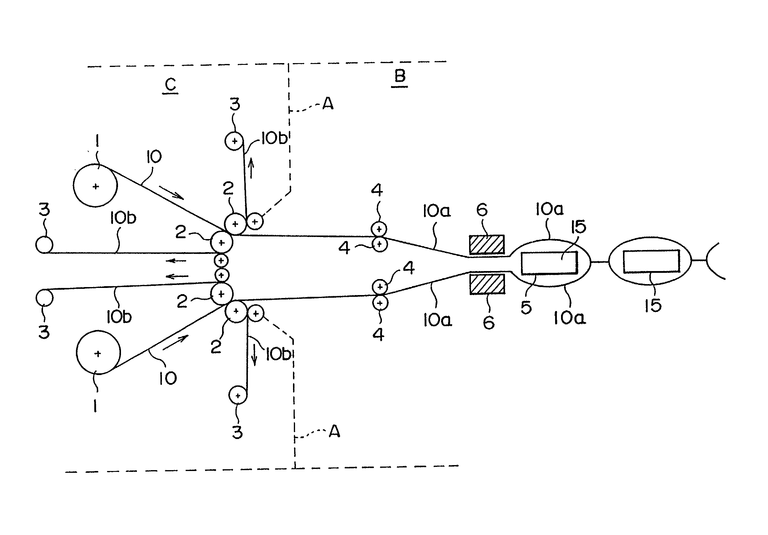
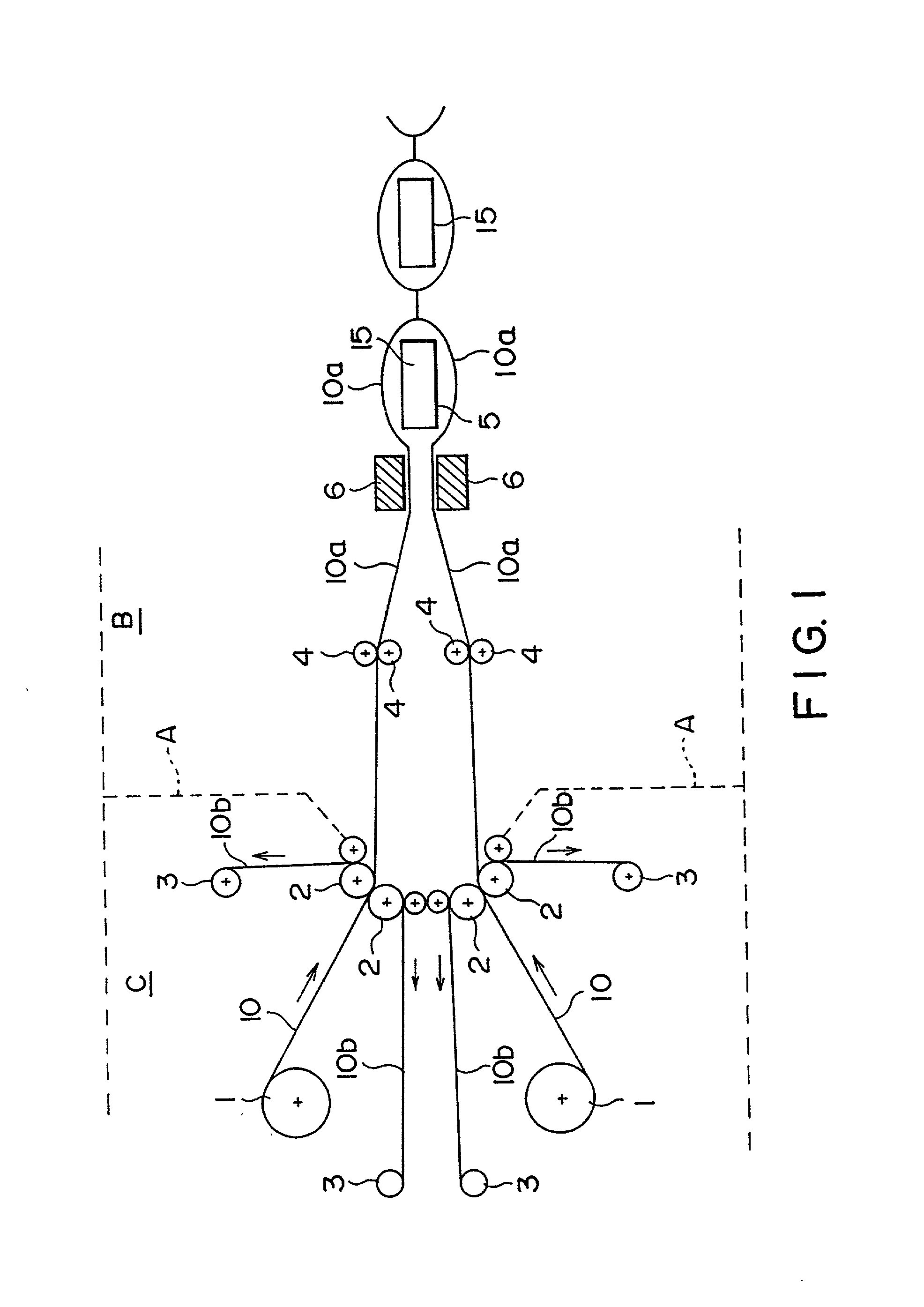
[0046] FIG. 1 is a schematic diagram showing the construction of a dustfree filling and sealing apparatus according to a first embodiment of the present invention.

[0047] As shown in the figure, the dustfree filling and sealing apparatus comprises a pair of wrapping clean film supply means 1, a pair of outer layer film peeling-off means 2, a pair of outer layer film winding means 3, a pair of inner layer film conveying means 4, an object filling means 5, and an impulse seal head 6. The impulse seal head 6 seals two inner layer films 10a into which an object is inserted.

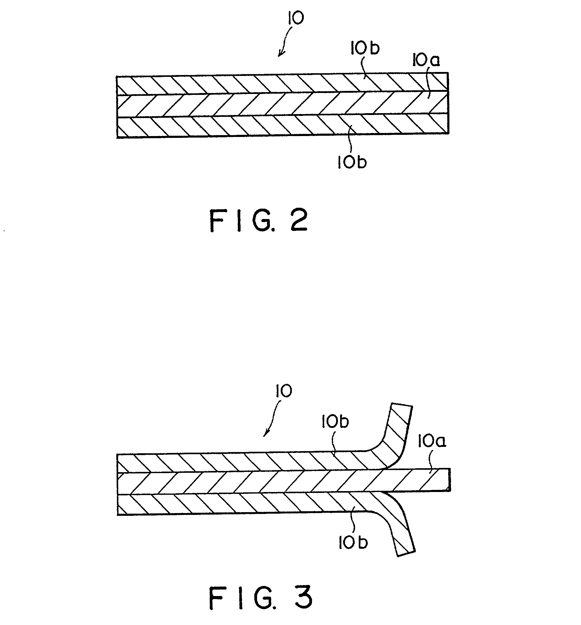
[0048] A wrapping clean film 10 is supplied from each of the wrapping clean film supply means 1. As shown in FIG. 2, the wrapping film 10 is composed of at least one inner layer film 10a and two outer layer films 10b which are co-extruded. The outer ...

second embodiment

[0067] Second Embodiment

[0068] 2-1 Basic Construction

[0069] Next, a clean film producing method according to a second embodiment of the present invention will be described. A resin which forms an inner layer film and another resin which forms outer layer films which is applied to the inner layer film for peelably coating the front and rear surfaces of the inner layer film are co-extruded in a molten state from an extruder by for example T-die method. Thus, as shown in FIG. 4, one inner layer film 21 and two outer layer films 2 are laminated.

[0070] The co-extruding temperature is 230.degree. C. or below, preferably 220.degree. C. or below. This is because when the co-extruding temperature exceeds 230.degree. C., the peeling property of the outer layer films 22 to coat the front and rear surfaces of the inner layer film 21 may deteriorate.

[0071] The inner layer film 21 is used for a wrapping material which is directly in contact with an object such as a semiconductor product. When the...

compared example 2

[0087] A three-layered co-extruded film was produced in the same manner as the practical example 1 except that the co-extruding temperature was 240.degree. C. instead of 220.degree. C.

[0088] Next, the inter-layer peeling strength of the three-layered co-extruded film was measured in the same manner as the practical example 1. The measured result is shown in Table 2-1.

Evaluation of Measured Results

[0089] As is clear from Table 2-1, the inter-layer peeling strength of the three-layered co-extruded film produced in the practical example 1 is much smaller than that of the three-layered co-extruded films produced in the compared examples 1 and 2. Thus, it was revealed that the three-layered co-extruded film produced in the practical example 1 is suitable for a clean film.

[0090] 2-3 Effect

[0091] As described above, according to the second embodiment of the present invention, since a wrapping clean film which is composed of an inner layer film made of a low density polyethylene and two out...


PUM

PropertyMeasurementUnit
temperatureaaaaaaaaaa
densityaaaaaaaaaa
temperatureaaaaaaaaaa

Abstract

A dustfree filling and sealing apparatus is disclosed. A pair of wrapping clean films 10 which are free of cleaning are supplied from a pair of wrapping clean film supply means 1. Two outer layer films 10b are peeled off and removed from the wrapping clean films 10 by a pair of outer layer film peeling-off means 2. Thus, clean surfaces of inner layer films 10a appear. The two inner layer films 10a are conveyed by a pair of inner layer film conveying means 4 so that these films are opposed. An object 15 is inserted between the inner layer films 10a by an object filling means 5. The inner layer films 10a are sealed by an impulse seal head 6. The present invention also discloses a wrapping clean film producing method and a dustfree container.

Description

[0001] 1. Field of the Invention[0002] The present invention relates to a dustfree filling and sealing apparatus for wrapping such as a semiconductor product which is much delicately and adversely affected by dirt and dust and cloths for use in producing such a product. The present invention also relates to a dustfree container and a wrapping clean film producing method.[0003] 2. Description of the Related Art[0004] Since semiconductor products such as IC chips and LSI chips are much delicately and adversely affected by dirt and dust, they are produced in a clean room. In addition, wrapping materials which wrap products which are produced in such a clean atmosphere and cloths which are used in producing such products must be free of dirt and dust.[0005] Conventionally, wrapping materials are produced in a clean room and then cleaned with ultrapure water.[0006] In addition, a filling and sealing apparatus which automatically wrapping objects with such wrapping materials has been used...

Claims


Application Information

Patent Timeline
Patent Type & Authority Applications(United States)
IPC IPC(8): B29C48/08B29C48/18B29C59/10B29C65/00B29C65/78B32B7/06B32B27/12B65B9/02B65D77/20
CPCB29C47/0021Y10T156/1195B29C59/10B29C65/7894B29C66/022B29C66/723B29K2023/06B29K2023/083B29K2023/086B32B7/06B32B27/12B65B9/02B65D77/2032B65D2577/2025B29C66/45B29C66/53461B29C47/06B29C66/73711B29C66/73713B29C66/72341B29C66/72321B29C66/71B29C66/0222B29C66/112B29C66/1122B29C66/131B29C48/08B29C48/18B29K2077/00B29K2067/003B29K2029/04B29K2023/12B29K2023/0633B29K2023/0625B65D75/326B65D65/40
Inventor YAMAGUCHI, MASAHISAYAMAMOTO, HIROSHIOTSUKA, KOJI
Owner DAI NIPPON PRINTING CO LTD
Why Eureka
Try Eureka