

Direct current commutator motor
a commutator motor and direct current technology, applied in current collectors, dynamo-electric components, electromagnetic interference suppression, etc., can solve the problems of reduced service life, unstable rectification, and inability to secure sufficient lifetim
- Summary
- Abstract
- Description
- Claims
- Application Information
AI Technical Summary
Benefits of technology
Problems solved by technology
Method used
Image

Examples
first embodiment
[0028] (First Embodiment)
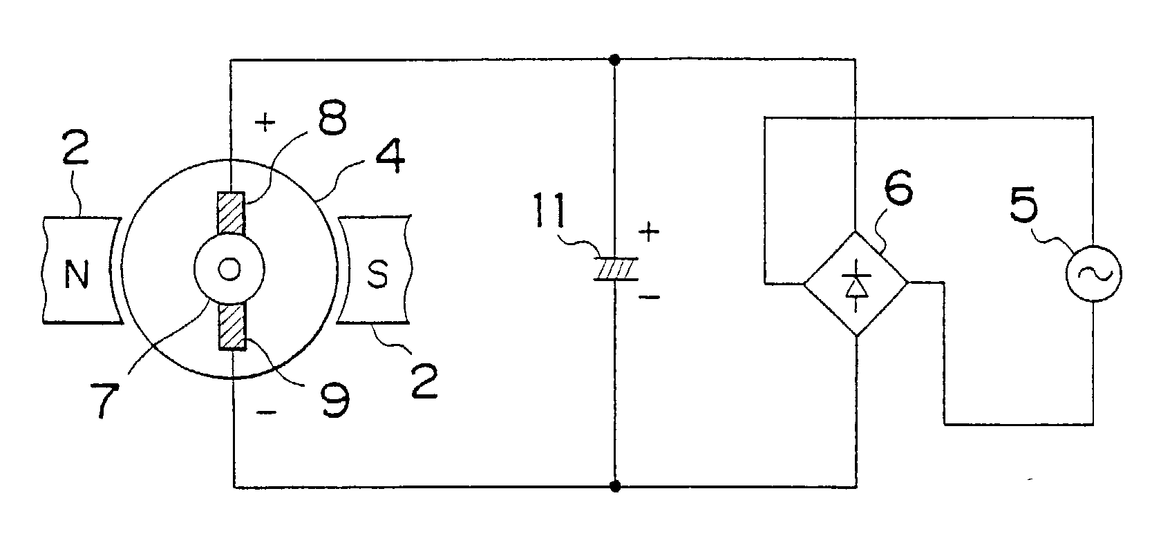
[0029] Referring to FIG. 1, reference numeral 5 represents an alternating current power source; reference numeral 6 represents a rectifier for full-wave rectifying an output from an alternating current power source and converting it into a pulsating current; reference numeral 8 represents a plus-side carbon brush; reference numeral 9 represents a minus-side metal-mixed graphite brush; and reference numeral 7 represents a commutator slidably engaged with the brushes and operable to selectively switching an electric current to be supplied to a rotor wire winding depending on the angular position thereof. Reference numeral 4 represents a rotor having the rotor wire winding (not shown) mounted therearound and to which an electric power is supplied with the electric current selected from commutator pieces. Reference numeral 2 represents a magnet built in a frame for generating an electromagnetic force in cooperation with the electric current flowing across the ro...
second embodiment
[0031] (Second Embodiment)
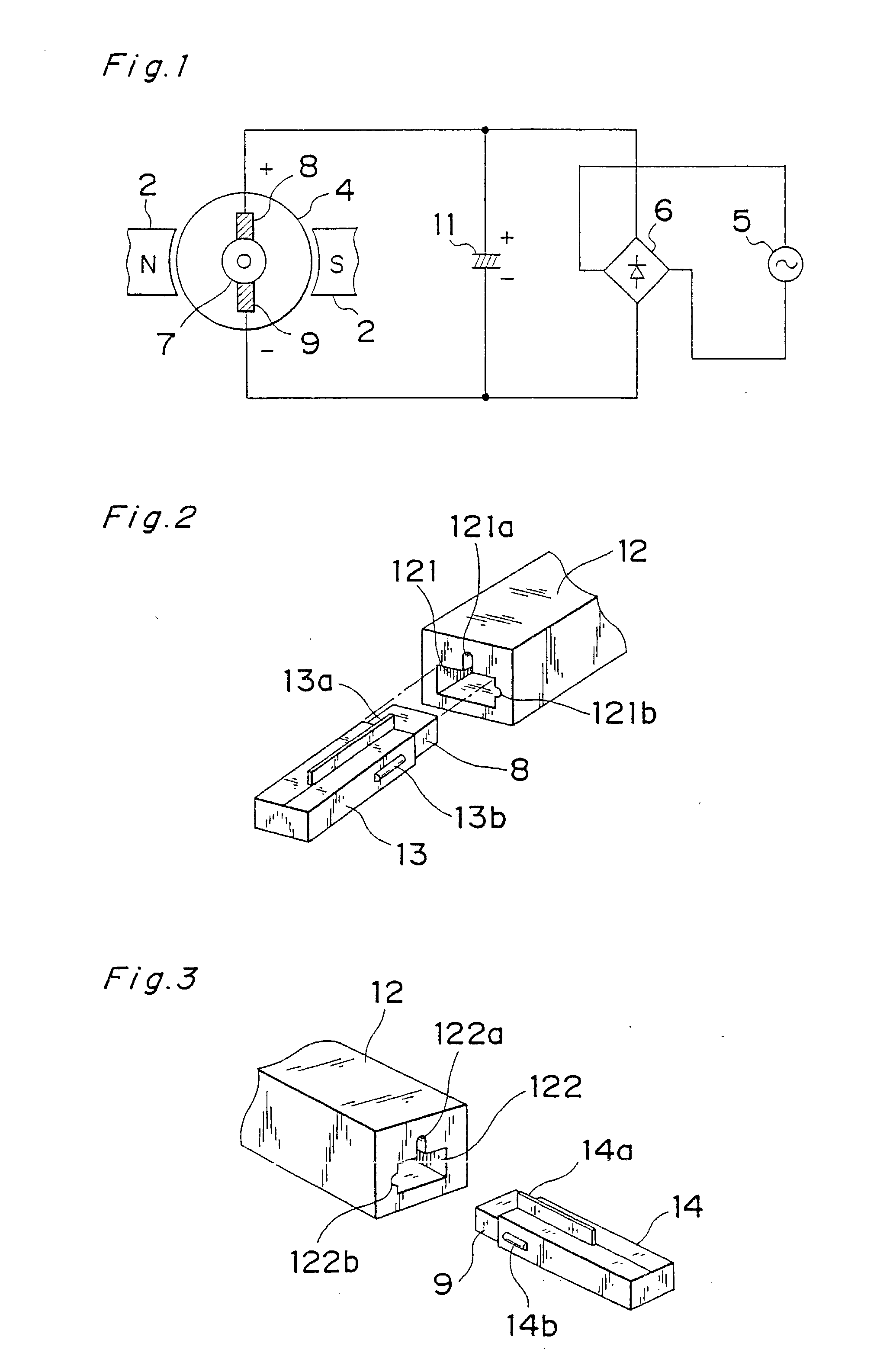
[0032] Referring now to FIGS. 2 and 3, reference numeral 13 represents a plus-side specials tube for receiving the plus-side brush 8; reference numeral 13a represents a first projection provided on the specials tube 13; and reference numeral 13b represents a second projection provided on the specials tube 13 and positioned at a location spaced 90.degree. from the first projection 13a in a counterclockwise direction as viewed from a direction of insertion of the plus-side brush 8. Reference numeral 14 represents a minus-side specials tube for receiving the minus-side brush 9; reference numeral 14a represents a first projection provided on the specials tube 14; and reference numeral 14b represents a second projection provided on the specials tube 14 and positioned at a location spaced 90.degree. from the second projection 14a in a clockwise direction as viewed from a direction of insertion of the minus-side brush 9.
[0033] Reference numeral 12 represents a bra...
third embodiment
[0036] (Third Embodiment)
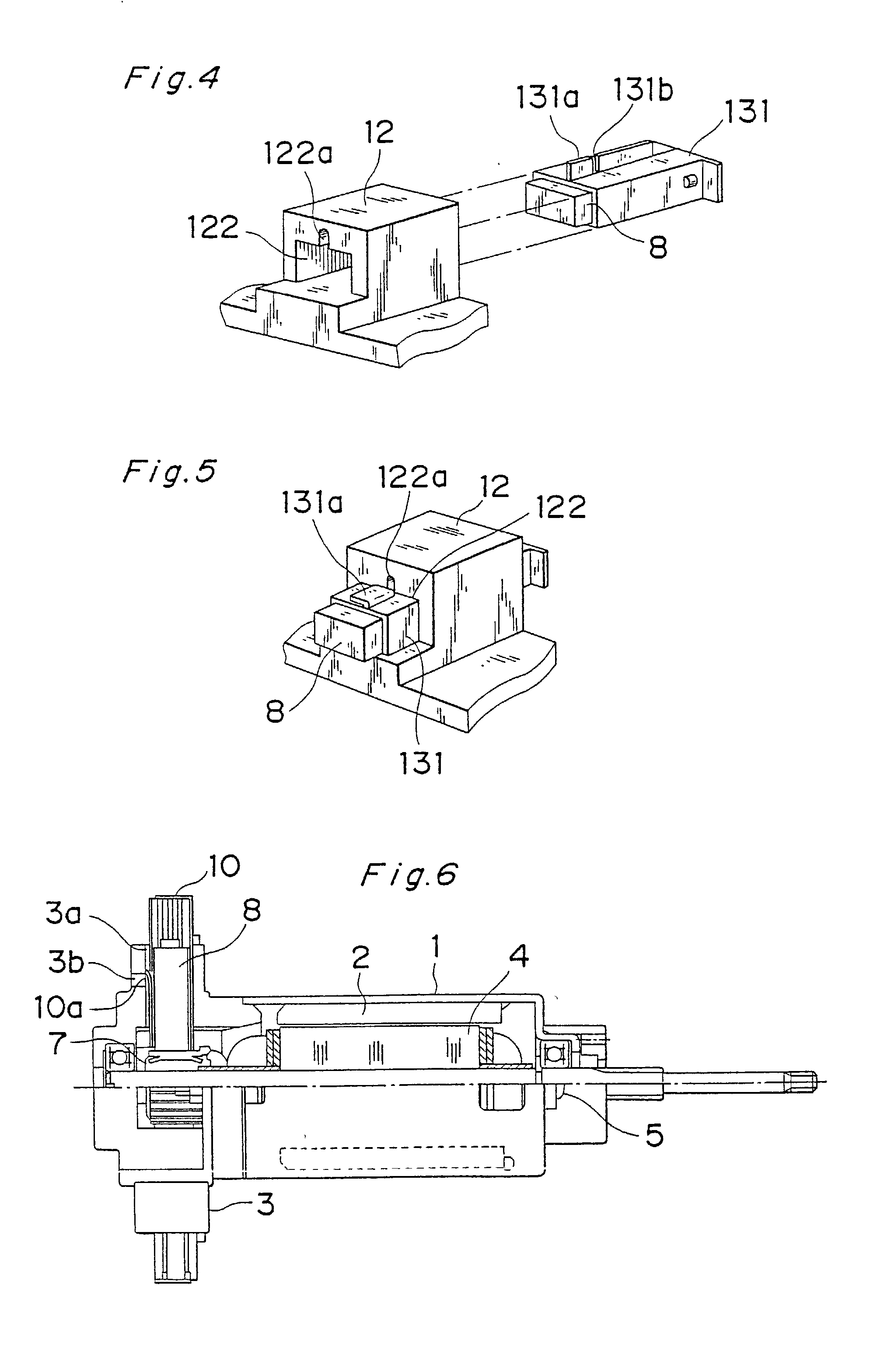
[0037] Referring to FIGS. 4 and 5, reference numeral 131 represents a specials tube for slidably receiving the brush 8; reference numeral 131a represents a bendable portion of a tab provided on a side surface of the specials tube 131; reference numeral 131b represents a crevice separating the bendable portion 131a from the rest of the tab; reference numeral 12 represents a bracket made of a thermosetting resin; reference numeral 122 represents an insertion hole defined in the bracket 12 for receiving the specials tube 131; and reference numeral 122a represents a longitudinal groove defined in the bracket 12 in communication with the insertion hole 122 for accommodating the tab on the specials tube 131 with a slight gap formed therebetween and so sized and so configured as to permit the bendable portion 131a to be exposed to the outside.
[0038] According to the third embodiment, after the specials tube 131 has been inserted into the insertion hole 122, the ben...
PUM
 Abstract
Description
Claims
Application Information