Heat exchanger garment

a technology of heat exchanger and garment, which is applied in the field of heat exchanger garment, can solve the problems of excessive heat loss, increased risk of infection, and increased risk of infection, and achieve the effects of improving patient comfort, low cost, and being soft to touch

Inactive Publication Date: 2003-04-10
M T R E ADVANCED TECH
View PDF3 Cites 43 Cited by
  • Summary
  • Abstract
  • Description
  • Claims
  • Application Information

AI Technical Summary

Benefits of technology

[0016] A preferred heat exchanger in accordance with the invention is such wherein each of the internal and the external layers is constructed of two layers; namely the garment is a four-layered structure. This four-layered structure consists of two impermeble sheets lining said space overlaid by usually heavier reinforcing layers. All four layers are typically made of a heat-weldable material and are point welded to one another. The two innermost layers serve to define the fluid-tight space, while the outer layers reinforce the structure and allow the application of an increased internal fluid pressure, at times up to about 3 Atm without rupturing. Increase pressure may at times be of importance to ensure a certain level of flow of the heat-control fluid within the garment's inner space. The inner layers of the heat exchange may be made of a polyethylene-based material such as Metallocene (manufactured by Dow Chemicals) sheeting, typically but not restricted to about 20-50 .mu.m thickness. The two outer layers are preferably somewhat hydrophilic to allow a certain degree of absorption of body and / or cleaning and disinfecting fluids and are also preferably soft to touch to ensure improved patient's comfort when contacting the skin. The outer layers may, for example, be made of a woven or non-woven spunbond fabric, e.g. made of polypropylene, having a characteristic weight of about 20 g / m.sup.2 to about 50 g / m.sup.2. The welding together of the four layers may be achieved, for example, by means of RF welding.
[0017] The heat exchanger having the aforementioned characteristics, is novel by itself (even when not formed into a garment as defined above), and forms an aspect of the present invention. The heat exchanger may be used for any application requiring a flexible heat exchanger with a relatively large heat exchange surface. A significant feature of the heat exchanger of this embodiment is that it is of low cost and high efficiency and has overall performance (heat exchange properties, flexibility, internal pressure resistance, and others) hitherto attained only with more complex and costly devices.
[0019] The garment is preferably designed such that each different section can be manipulated independently from other sections between an enveloping and a non-enveloping state. This has several advantages. For one, it allows easy accessibility to different parts of the body. Furthermore, this allows to use a single type of garment for different kinds of operations: for example in case of an operation performed on the subject's leg, the respective section will obviously be in the non-enveloping state while the other sections, namely those of the torso, the other leg, the arms, the neck, the head, etc., may be in an enveloping state. The feature of independent manipulation of the different sections between an enveloping and a non-enveloping state is typically achieved by emarginations in the garment's edges.
[0021] The above feature allows to provide an effective cover of the human body by the garment sufficient to properly control the body temperature, for a wide variety of different medical procedures. One should also note that effective heat transfer may be achieved regardless of the patient's position: whether he is placed lying on his back or whether he is placed with his back up or whether he is placed lying on his side, or even when positioned in a sitting position.

Problems solved by technology

Furthermore, under general anesthesia, the natural physiological mechanisms which operate to maintain a body temperature may fail, and the problem becomes particularly acute in cases where exposed internal body organs come into contact with the ambient air which results in excessive heat loss.
The problem is further aggravated by the fact that operation rooms are very often heavily cooled.
Similarly as human subjects, the problem of controlling body temperature is also experienced during surgical procedures performed on animals.
Overall, controlling the body temperature is one of the serious-problems facing the medical staff when performing operations.

Method used


Image

  • Heat exchanger garment
  • Heat exchanger garment
  • Heat exchanger garment

Examples


Embodiment Construction

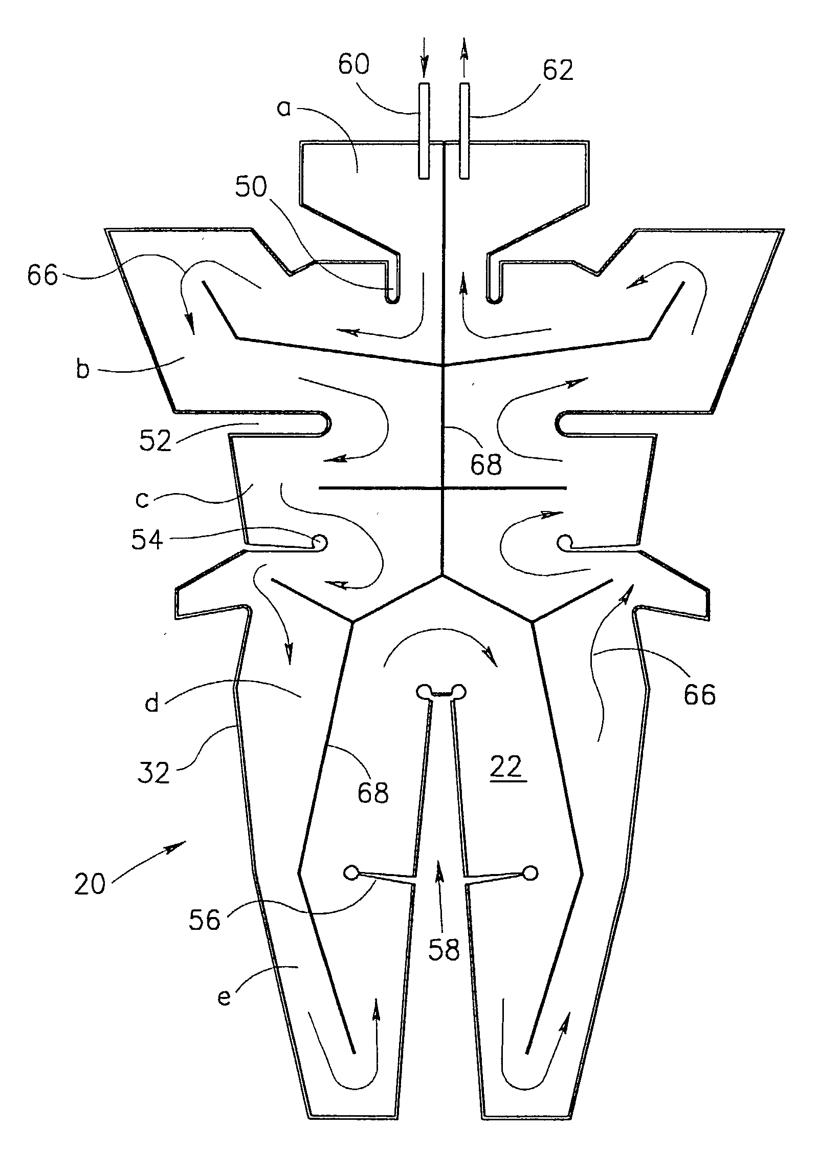
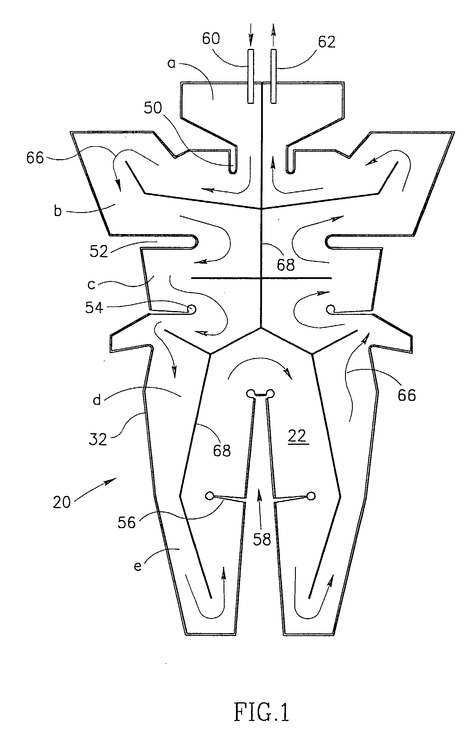
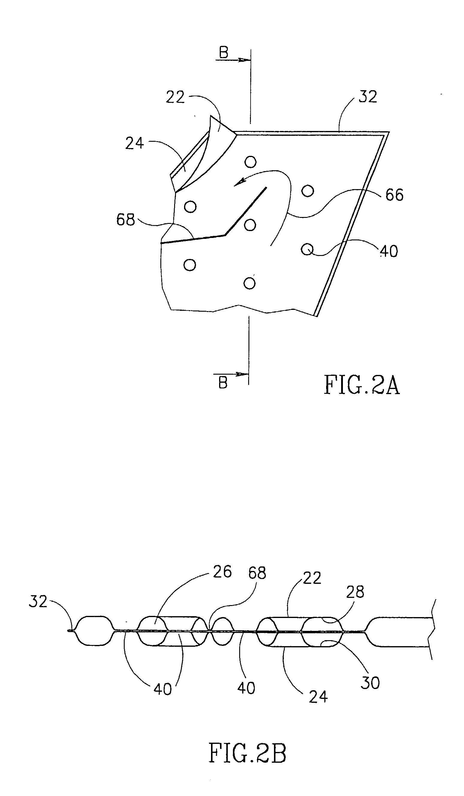
[0032] Reference is first being made to FIG. 1 showing a planar view of a garment generally designated 20 of which a part marked "II" in FIG. 1 is shown in a more enlarged view in FIG. 2A and of which a cross-section through lines B-B of FIG. 2A is shown in FIG. 2B. As can be seen in FIGS. 2A and 2B, the garment has an internal, body-facing layer 22 and an external layer 24 which define between them a fluid-tight space 26. Each of the layers 22, 24 is made from a thermoplastic material with a heat weldable, space-lining face 28, 30 (see FIG. 2B). The two layers are welded to one another in fluid tight manner at the edges 32.

[0033] The two layers 22, 24 are welded to one another at a plurality of weld points 40 seen in FIGS. 2A and 2B.

[0034] The weld points 40 cause a flow disturbance and consequently the flow of liquid through the garment (see description below) becomes uniform throughout the entire space of the flow path (see below).

[0035] The garment is symmetrical along a longitu...


PUM


Abstract

A heat exchanger for use in controlling subject's body temperature during a medical procedure comprises a flexible garment adapted for enveloping portions of the subject's body surface with dedicated sections for enveloping different body parts. Defined within the garment is a continuous, fluid tight space, wherein a flow path for heat-control fluid is defined between fluid inlet and fluid outlet. The inner faces of the garment's internal and external layers are made of a heat-weldable material and are point-welded to one another at a plurality of locations throughout the garment with a distance between two adjacent points being between about 8 to about 20 mm.

Description

[0001] The present invention relates to a heat exchanger which is intended to be applied onto a subject's body for controlling the subject's body temperature during medical procedure.BACKGROUND OF THE INVENTION AND PRIOR ART[0002] There are a variety of medical procedures in which a subject's body temperature has to be controlled. For example, during open heart surgery, the body temperature has to be controllably reduced to about 35.degree. C. and then at the end of the operation increased back to normal body temperature. Furthermore, under general anesthesia, the natural physiological mechanisms which operate to maintain a body temperature may fail, and the problem becomes particularly acute in cases where exposed internal body organs come into contact with the ambient air which results in excessive heat loss. The problem is further aggravated by the fact that operation rooms are very often heavily cooled. Following surgical procedure, it may take some time until the body acquires ...

Claims


Application Information

Patent Timeline
Patent Type & Authority Applications(United States)
IPC IPC(8): A61F2/00A61F7/00A61F7/02
CPCA61F7/02A61F2007/0288A61F2007/0054A61F2007/0001
Inventor KUSHNIR, IGAL
Owner M T R E ADVANCED TECH
Why Eureka
Try Eureka