System for driving electric motor

a technology of electric motor and system, applied in the direction of motor/generator/converter stopper, dynamo-electric gear control, dynamo-electric converter control, etc., can solve the problems of step-out detection, method of determining effective value, condition setting

Inactive Publication Date: 2003-04-17
HITACHI LTD
View PDF5 Cites 22 Cited by
  • Summary
  • Abstract
  • Description
  • Claims
  • Application Information

AI Technical Summary

Problems solved by technology

However, in the first known example, the method of determining the effective value of the current for use in the discrimination of the step-out is difficult, and also there is the possibility that even when the electric motor is driven in the state of the overload, the step-out is detected by mistake.
In particular, in the condition of driving the electric motor with the power factor of the field system weakening region or the like being reduced, the condition setting is difficult.
In addition, it is necessary to carry out the root arithmetic operation of the square root of the total sum of the phase currents squared in the arithmetic operation of the current effective value, and the processing of this arithmetic operation is difficult to be executed using a low cost controller (microcomputer).
In addition, in the case where the electric motor is stopped at a stretch due to the abrupt load disturbance, since there is no difference between the applied frequency and the electric motor current, it is impossible to detect the step-out.
Further, as the problem in terms of a configuration of a controller, the dedicated timer for determining the cycle of the current is required, and hence there arises the problem that the system becomes complicated.
While in the third known example, the detection of the step-out is carried out on the basis of the magnitude of the exciting current component (d-axis component) of the electric motor, since the magnitude of the exciting current is changed in the transient time during the load disturbance or the like, in this case as well, there is the possibility that the wrong detection of the step-out may be carried out.
Also, since during the step-out, the difference occurs between the magnetic pole axis assumed in the controller and the true magnetic pole axis of the electric motor, the exciting current which is observed on the coordinate axes on the control side is not necessarily the proper exciting current component, and hence there is the possibility that the wrong detection of the step-out may be carried out.
In the above-mentioned first and third known examples, a point of employing the changing current effective value, power factor, exciting current or the like in the normal operation as well is a problem, and also even if any of the physical quantities is employed, the discrimination of the step-out state is difficult.

Method used


Image

  • System for driving electric motor
  • System for driving electric motor
  • System for driving electric motor

Examples


first embodiment

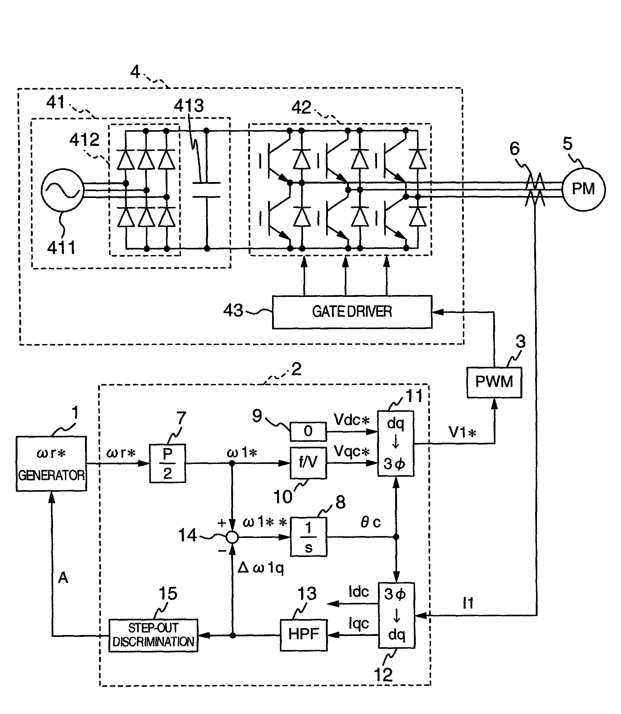
[0033] FIG. 1 is a circuit diagram, partly in block diagram, showing a configuration of a system for driving a permanent magnet type synchronous motor according to the present invention. In FIG. 1, reference numeral 1 designates a speed command generator for issuing a rotational speed command .omega.r* to an electric motor; reference numeral 2 designates a controller for operating arithmetically applied voltages to the electric motor; reference numeral 3 designates a PWM (Pulse Width Modulated Wave) generator for generating a pulse used to drive an inverter 4 on the basis of a voltage command V1*; reference numeral 4, the inverter for driving the electric motor; reference numeral 5, a permanent magnet type synchronous motor as a subject of the control; and 6, a current detector for detecting currents of the electric motor 5.

[0034] The controller 2 includes a conversion gain (P is the number of poles of the electric motor) 7 for converting the rotational speed command .omega.r* to an...

second embodiment

[0048] FIG. 6 shows the present invention.

[0049] As for the method of driving the permanent magnet type synchronous motor in the speed / position sensorless manner, there is known the sensorless / vector control method. In the case of the sensorless / vector control method, the d-q axes with the magnetic pole axis of the electric motor as the reference matches stationarily the dc-qc-axes in the controller, and hence it is possible to realize the linearity, the optimization of the efficiency, and the like. The second embodiment of the present invention relates to the step-out detection in this sensorless / vector control method.

[0050] FIG. 6 shows a configuration of the sensorless / vector controller having the step-out detector provided therein. A controller 2A shown in FIG. 6 is employed instead of the controller 2 shown in FIG. 1, whereby it is possible to realize the second embodiment of the present invention.

[0051] In FIG. 6, the constituent elements designated with reference numerals 7 t...

third embodiment

[0064] FIG. 7 shows the present invention.

[0065] Though since in the above-mentioned first and second embodiments, the step-out detection is carried out using .DELTA..omega.1q and .DELTA..theta.c which are changed in the step-out, the certainty of the step-out discrimination is enhanced, there arises the following problem. That is, when the load disturbance is very large and hence the rotation of the electric motor is stopped in an instant, the back electromotive force of the electric motor becomes zero at a stretch so that the vibration phenomenon of the above-mentioned .DELTA..omega.1q or .DELTA..theta.c does not occur. In other words, the above-mentioned first and second embodiments are not suitable for the use in which the electric motor gets into the step-out by the abruptly applied load to be stopped. In the third embodiment of the present invention, the step-out detecting method with which the above-mentioned problem is solved is provided.

[0066] In FIG. 7, the constituent ele...


PUM


Abstract

An electric motor driving system has a permanent magnet type synchronous motor, an inverter for driving the motor, a generator for issuing a rotational frequency command to the motor and a controller including a conversion gain for generating a control signal to the inverter on the basis of the rotational frequency command, an integrator, a zero generator, a qc-axis voltage command arithmetic unit, a dq inverter, a dq coordinate converter, a high-pass filter, and an adder, wherein the system includes the high-pass filter for correcting the rotational frequency command to the motor on the basis of current detection values flowing through the motor, and a step-out detector for comparing the correction amount with a threshold value previously set for the coordinate amount to judge when the correction amount exceeds the threshold value at least one or more times that the motor is in the step-out state.

Description

[0001] 1. Field of the Invention[0002] The present invention relates in general to a system for driving a permanent magnet type synchronous motor (PM motor). More particularly, the invention relates to the technology for detecting the step-out of an electric motor, when carrying out the control of the rotational frequency of an electric motor, without employing a sensor for detecting the speed / position of an electric motor.[0003] 2. Description of the Related Art[0004] Heretofore, with respect to the method of detecting the step-out of a permanent magnet type synchronous motor which is driven without a sensor for detecting the speed / position of an electric motor, there is known the technology disclosed in JP-A-9-294390 and JP-A-2001-25282.[0005] A first known example (JP-A-9-294390) is such that an effective value of a current which is caused to flow through an electric motor and a power factor are arithmetically operated to discriminate the presence or the absence of the step-out. ...

Claims


Application Information

Patent Timeline
Patent Type & Authority Applications(United States)
IPC IPC(8): H02P6/06H02P6/18H02P6/08H02P6/12H02P6/182H02P6/28H02P21/00H02P21/22H02P27/04H02P27/08
CPCH02P6/12
Inventor IWAJI, YOSHITAKAENDO, TSUNEHIROSAKAMOTO, KIYOSHIOKUBO, TOMOFUMI
Owner HITACHI LTD
Why Eureka
Try Eureka