Bus repeater

a bus and repeater technology, applied in the field of bus repeaters, can solve the problems of high cost of bus repeaters, unsatisfactory delays in signal transmission between respective linked buses,

Inactive Publication Date: 2003-04-17
FESTO AG & CO KG
View PDF5 Cites 26 Cited by
  • Summary
  • Abstract
  • Description
  • Claims
  • Application Information

AI Technical Summary

Benefits of technology

[0008] The bus-repeater is compact in design and may be manufactured using low priced components so that for instance it can be integrated in one connecting plug for the connection of two or more buses. The bus-repeater may be manufactured using separate components or, in an advantageous form thereof, in the form of an integrated circuit, it then not requiring any expensive components, as for example a microcontroller. Furthermore, no Baud rate setting of the bus-repeater is necessary, since such rate is more or less automatically adapted to the respective Baud rates.
[0011] Owing to the above explained decay of signal pulses and therefore their prolongation wait times, during which times the bus-repeater is unable to transmit a renewed signal pulse. In the case of high Baud rates and in extreme cases wait times may occur, which are approximately 50% of the intended duration of the respective pulse. Therefore the bus-repeater will preferably comprise unloading means for unloading the first bus and / or the second bus after completion of transmission of a signal pulse to the first bus or, respectively, the second bus so that the decay time of the signal pulses is shortened and signal pulse transmission may be resumed. In the case of the CAN bus a state change from dominant to recessive is accordingly accelerated.
[0015] More particularly when the unloading means are activated during the entire overrun time of the locking means it is an advantage to provide a common timer for the unloading means and the locking means for the formation an overrun time pulse.

Problems solved by technology

This leads to undesired delays during signal transmission between the respectively linked buses.
Furthermore, known bus-repeaters are expensive owing to the necessary microcontrollers.

Method used


Image

  • Bus repeater
  • Bus repeater
  • Bus repeater

Examples


Embodiment Construction

.

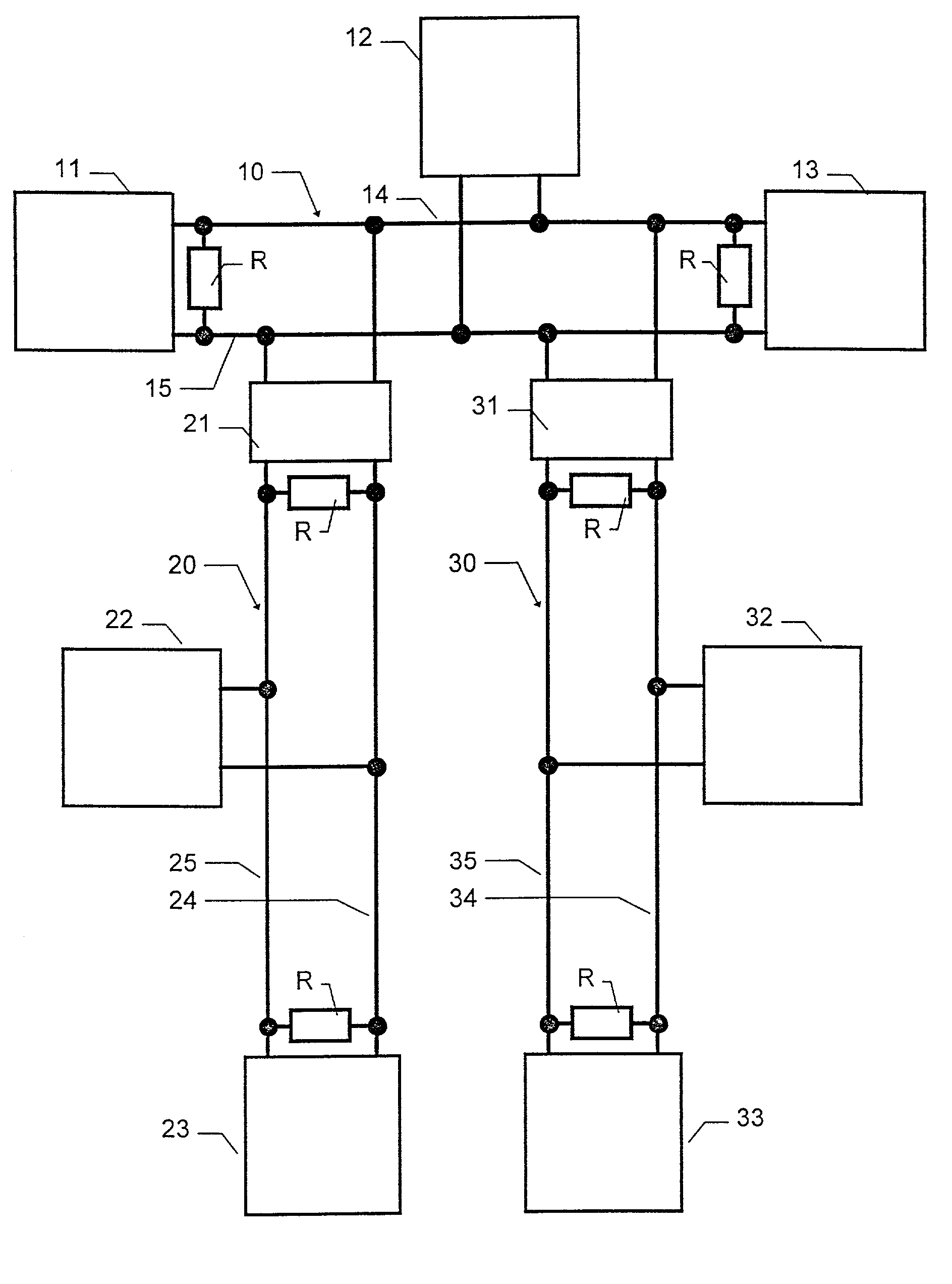
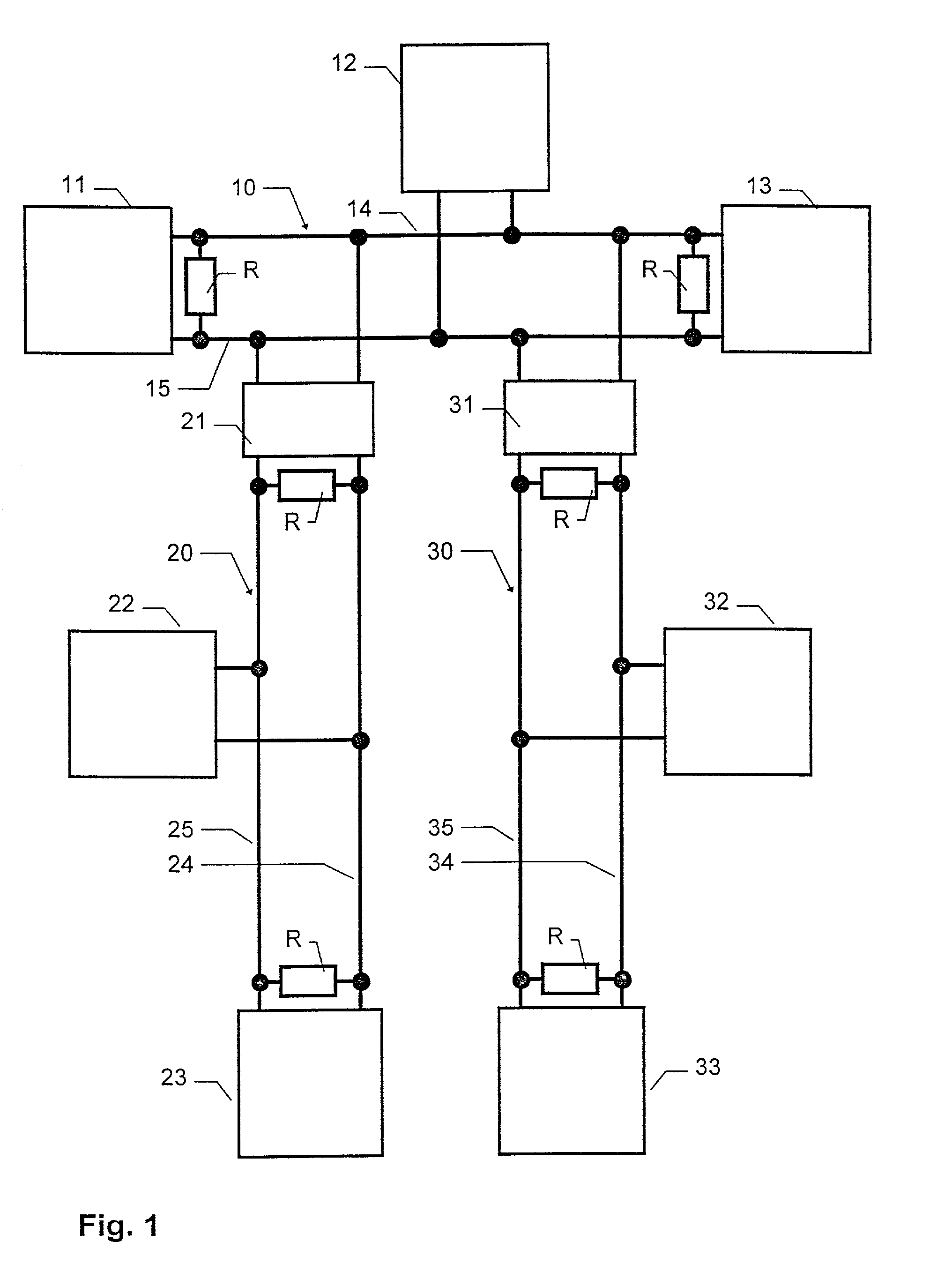
[0022] FIG. 1 depicts a bus 10, which in the present case is a CAN bus, with connected bus traffic participants 11, 12 and 13. In the case of such bus participants 11, 12 and 13 it is a question for example of control device for fluid power valve arrangements, which communicate with one another by way of the bus 10. Moreover, CAN buses 20 and 30 are connected to the bus 10 by way of bus-repeaters 21 and, respectively, 31, which in the present case are of identical design. The bus 20 serves as a communication medium for the bus participants 22 and 23, whereas the bus 30 serves the bus participants 32 and 33. The bus participants 22 and 23 and furthermore 32 and 33 are for example local control means, which are associated with the bus participants 11 and respectively, 13. The buses 10, 20 and 30 possess bus lines 14, 15, 24 and 25 and, respectively, 34 and 35, which are each terminated by terminal resistors R at the bus end. The bus line 14 serves as a CANH lines ("CAN high") and the...


PUM


Abstract

A bus-repeater for coupling at least one first bus with a second bus, by way of which data may be transmitted in the form of serial digital signal pulse sequences and including at least one first and a second transmit-receive means, with which the first and, respectively, the second bus may be coupled and by way of which the bus-repeater may transmit signal pulse sequences, received via the first bus on the second bus, and vice versa. In accordance with the invention the bus-repeater comprises locking means, which during transmission of a signal pulse received from the first bus to the second bus lock transmission by the bus-repeater of signal pulses, received from the second bus, via the first bus for a transmission locking time and vice versa.

Description

BACKGROUND OF THE INVENTION.[0001] The invention relates to a bus-repeater for coupling at least one first bus to a second bus, by way of which data are transmitted as serial digital signal pulse sequences, comprising at least one first and a second transmit-receive means, to which the first and, respectively, the second bus may be coupled and by way of which the bus-repeater may transmit signal pulse sequences received from the first bus via the second bus and vice versa.[0002] Such a bus, along which data are transmitted as serial, digital signal pulse sequences, is for instance a CAN bus (CAN standing for Controller Area Network). Along such transmission lines termed "CAN high" and "CAN low" transmissions lines one respective participant may transmit digital signal pulse sequences, which are then received by all participants including the transmitting participant. In the case of the CAN protocol a distinction is drawn as regards a signal pulse between two logical states: the bits...

Claims


Application Information

Patent Timeline
Patent Type & Authority Applications(United States)
IPC IPC(8): H04L5/14
CPCH04L5/1461
Inventor KRAMER, JOACHIMAICHELE, ALEXANDER
Owner FESTO AG & CO KG
Why Eureka
Try Eureka