Power supply/demand control system

a power supply/demand control and power supply technology, applied in process and machine control, electric devices, instruments, etc., can solve the problems of low final energy efficiency, large loss of electric power transmission from electric power stations to consumers, low energy efficiency, etc., to balance the supply and demand of electric power, and reduce the selling price of electric power

Inactive Publication Date: 2003-04-24
PANASONIC CORP
View PDF19 Cites 87 Cited by
  • Summary
  • Abstract
  • Description
  • Claims
  • Application Information

AI Technical Summary

Benefits of technology

0084] (2) When electric power flows from the electric power transmission lines 150 to the electric power transmission lines 40, the price setting apparatus 130 lowers the selling price of electric power.
0085] (3) In the cases other than the cases (1) and (2), and in the case when the total of the amount of electric power flowing from the electric power transmission lines 40 to the electric power transmission lines 150 (this becomes a minus value when electric power flows from the electric power transmission lines 150 to the electric power transmission lines 40) and the amount of electric power flowing from the electric power transmission lines 40 to the electric power transmission lines 50 is larger than zero, the price setting apparatus 30 raises the selling price of electric power. (4) In the cases other than the cases (1) and (2), and in the case when the total of the amount of electric power flowing from the electric power transmission lines 150 to the electric power transmission lines 40 (this becomes a minus value when the electric power flows from the electric power transmission lines 40 to the electric power transmission lines 150) and the amount of electric power flowing from the electric power transmission lines 50 to the electric power transmission lines 40 is larger than zero, the price setting apparatus 30 lowers the selling price of electric power.
0086] In the above-mentioned embodiment, the supply and the demand of electric power are balanced by changing the selling price of electric power used as information for increasing / decreasing the amount of electric power supply; however, the supply and the demand may be balanced by changing the purchase price of electric power used as information for increasing / decreasing the amount of electric power supply or by changing both the selling price and the purchase price of electric power used as information for increasing / decreasing the amount of electric power supply.

Problems solved by technology

In this kind of large electric power generation system, heat generating simultaneously with electric power generation cannot be used, and the loss of electric power transmission from electric power stations to consumers is large, whereby the final energy efficiency is low.
Particularly in household consumers having many distributed loads with low amount of electric power consumption, energy efficiency becomes low.
Even in this kind of distributed electric power generation, if the sale of electric power to a commercial electric power system is carried out regardless of the present electric power demand, a transmission loss occurs in the case when a node that sells electric power is distant from an electric power supplier who purchases the electric power; however, conventionally, electric power should only be generated at one location and transmitted efficiently to locations near consumers; hence, if contractors who sell electric power are few, the transmission system is not affected greatly.
However, if each node sells extran electric power, transmission cost changes greatly depending on the distributions of electric power selling locations and electric power consuming locations.
For this reason, when electric power is generated at a node, such as a dwelling house, wherein electric power demand greatly changes depending on time, season, or the like, the amount of electric power generated by the fuel cell cannot be controlled promptly depending on the change in the electric power demand at the node, whereby generated electric power becomes excessive or lacking.
This causes a problem, that is, the above-mentioned node must purchase lacking electric power from the outside in spite of having an electric power generator or sell excessive electric power to the outside.

Method used


Image

  • Power supply/demand control system
  • Power supply/demand control system
  • Power supply/demand control system

Examples


example 4

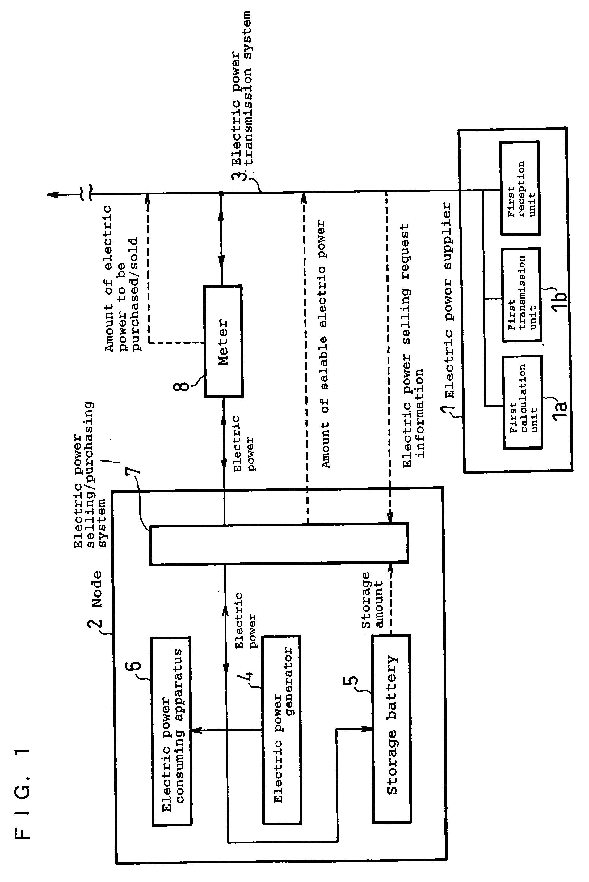
[0098] FIG. 5 is a view showing the configuration of an electric power supply and demand management system in accordance with Embodiment 4 of the present invention. Embodiment 4 shown in FIG. 5 is the same as Embodiment 1 in that each node has electric power consuming apparatuses, an electric power generator and a storage battery, but different in that the operation of the electric power selling / purchasing system is determined depending on voltage by using the fact that the voltage changes depending on electric power supply and demand situation. In other words, the voltage lowers when electricity is supplied to a nearby node via the transmission lines, and the voltage rises when electricity is supplied reversely; hence, electric power may be sold when the voltage is low, and electric power may be prevented from being sold when the voltage is high.

[0099] More specifically, the electric power selling / purchasing system 7 determines as to whether electric power is sold or not depending ...

embodiment 5

[0103] Embodiment 5

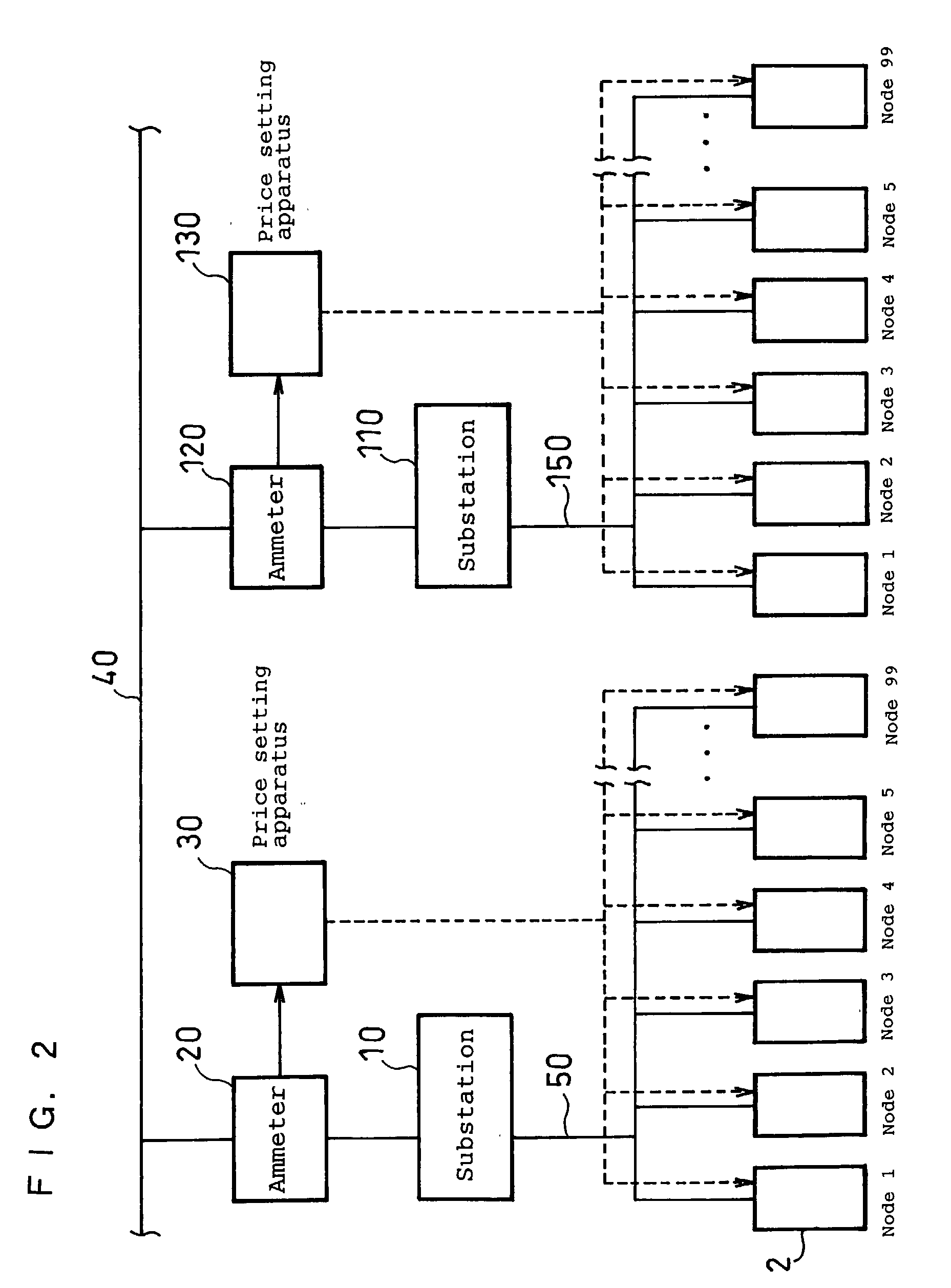
[0104] FIG. 7 is a view showing the configuration of an electric power supply and demand management system in accordance with Embodiment 5 of the present invention. In the electric power supply and demand management system of this embodiment, twp nodes 101 and 201 are included in one group. In FIG. 7, a fuel cell 104 and a fuel cell 204 used as electric power generators are shown separately from the node 101 and the node 201, respectively, for the sake of convenience; however, they are included in the node 101 and the node 201, respectively, actually.

[0105] Furthermore, when the amounts of electric power consumption at the nodes are measured by electric power distribution boards 102 and 202, respectively, as shown in FIG. 7, an electric power consuming apparatus, which receives electric power supplied from the corresponding distribution board, or a set of such electric power consuming apparatuses becomes a node; this is advantageous in that the amounts of electric...

embodiment 6

[0123] Embodiment 6

[0124] The above Embodiment 5 in accordance with the present invention can be attained with the use of circuits; however, the present invention can also be attained with the use of a CPU, memory and peripheral circuits. In this case, the flowchart of a program for determining the operation of the CPU is shown in FIG. 9. Step 1 is to realize the storage means 301, step 2 is to realize the predicting means 302, step 3 is to realize the supplied amount determining means 303, and step 4 is to realize the supply control means 304. These steps are not always required to be carried out in the above order. Furthermore, operation is carried out at intervals of 10 minutes in FIG. 9; however, the operation may be carried out at intervals other than 10 minutes, and the operation may be carried out at intervals different from one another.

[0125] For example, step 1 to step 4 may be carried out as four processes independent from one another. In other words, process 1 and process...


PUM


Abstract

In order to effectively supply and demand electric power between an electric power supplier and a node or a group of nodes individually having an electric power generator, the present invention provides an electric power supply and demand management system capable of obtaining the difference between the total of electric power supplied from the electric power supplier to the node or group and the total of electric power consumed by the electric power loads of the node or group and capable of transmitting information for increasing/decreasing the amount of electric power supply so that the difference becomes smaller to the electric power supplier.

Description

[0001] The present invention relates to a distributed electric power generation system comprising an electric supplier and consumers for efficiently controlling and managing the supply and demand of electric power.[0002] In recent years, energy-saving measures have been taken significantly in view of environmental protection including the prevention of the greenhouse effect owing to carbon dioxide, although not so significantly as those during the oil crisis owing to oil shortage. Consumers of electric power are classified into industrial consumers and household consumers; the electric power consumption by the industrial consumers stays almost constant after 1970s, but the electric power consumption by the household consumers has increased twice or more after 1970s. Hence, additional energy-saving measures are required to be taken for household consumers.[0003] At present, the great majority of electric power generated by electric power supplier sides, such as hydraulic, thermal and...

Claims


Application Information

Patent Timeline
Patent Type & Authority Applications(United States)
IPC IPC(8): H02J3/00H02J3/06
CPCG06Q30/00G06Q50/06H02J3/008Y04S10/54Y04S10/545Y04S50/10Y02E40/76Y02E40/70Y04S10/50H02J3/06
Inventor KANBARA, TERUHISAGYOTEN, HISAAKITANIGAWA, HIDEKAZU
Owner PANASONIC CORP
Why Eureka
Try Eureka