
Connecting node

a node and connection technology, applied in the direction of rod connection, coupling, building scaffold, etc., can solve the problem of limiting the utilization of connectors in a single structure, and achieve the effect of optimum structural operation, fast and safe manner, and tight and safe connection

Inactive Publication Date: 2003-05-08
SABRITAS
View PDF4 Cites 1 Cited by
  • Summary
  • Abstract
  • Description
  • Claims
  • Application Information

AI Technical Summary

Benefits of technology

[0007] It is the object of the present invention to provide a connecting node from a simple structure and without involving outside elements which allows a rigid and safe connection among each of the elements integrating one structure.
[0008] It is another object of the present invention to provide a connecting node that allows joining of connecting nodes among each other, in a fast and safe manner.
[0009] It is another object of the present invention to provide a connecting node that allows anchoring of structural elements working under tension, such that with said elements the necessary structural tightness can be given to achieve optimum structural operation, once assembled.

Problems solved by technology

Furthermore, such connectors can only be assembled among each other as part of the structure configuration, discarding the possibility of joining each other with the object of allowing interaction among two or more similar characteristics structures, which limits connectors utilization in a single structure.

Method used


Image

  • Connecting node
  • Connecting node
  • Connecting node

Examples


Embodiment Construction

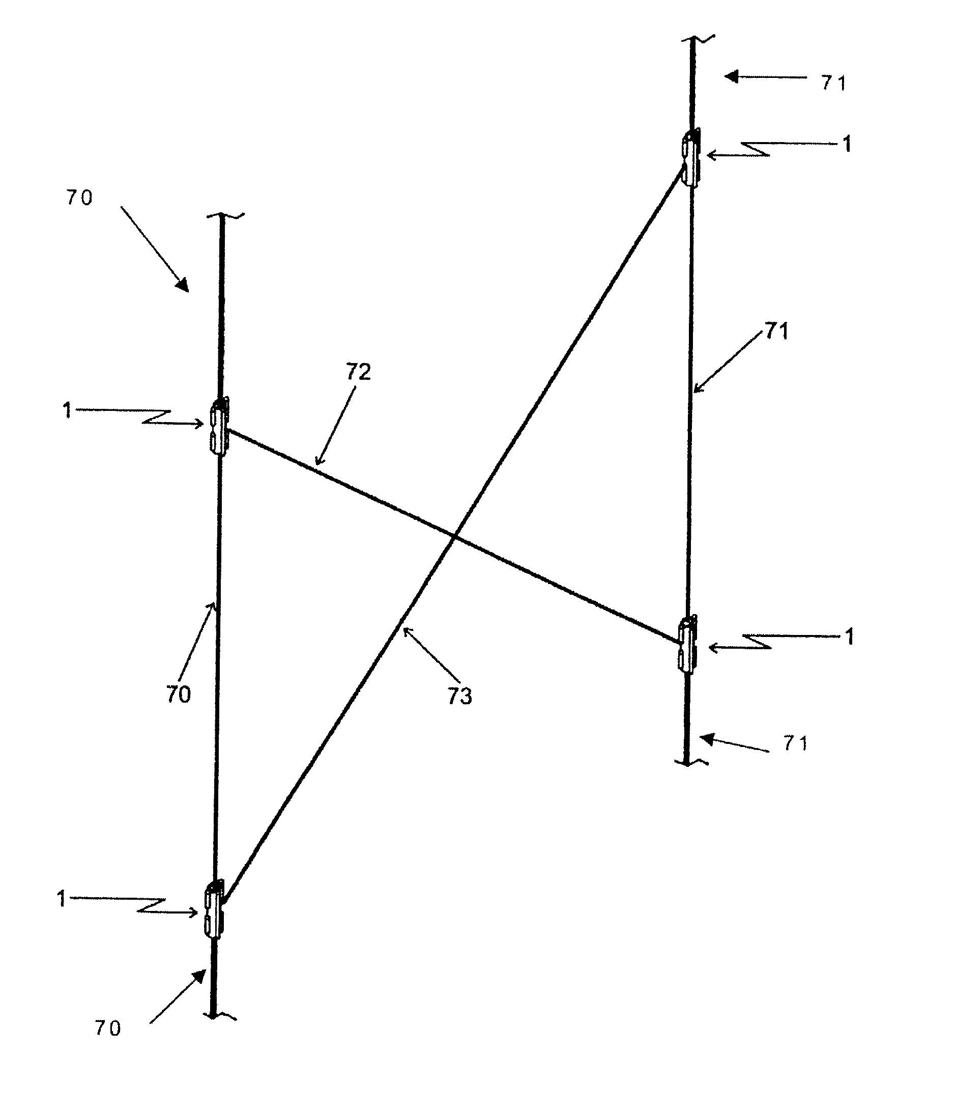
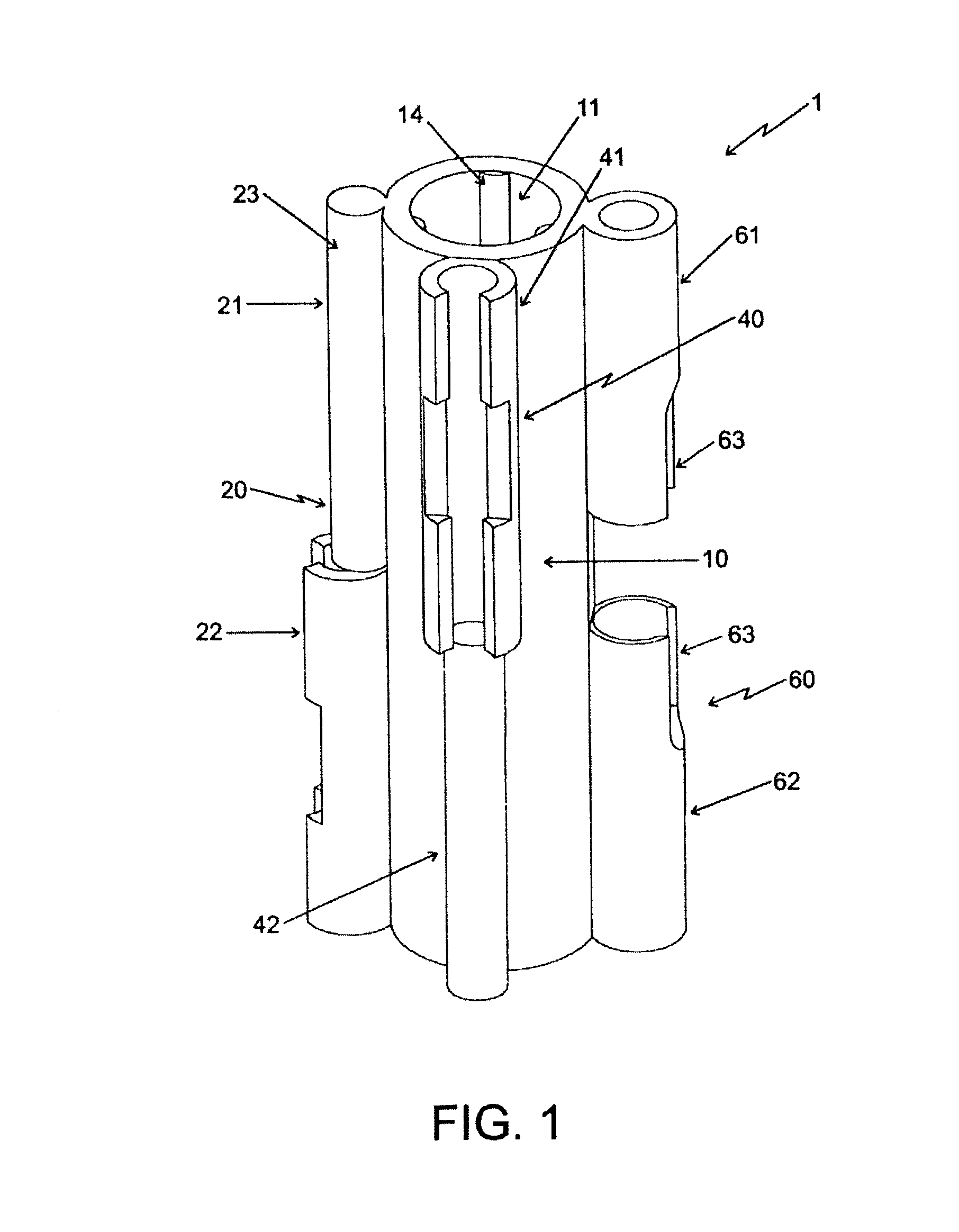
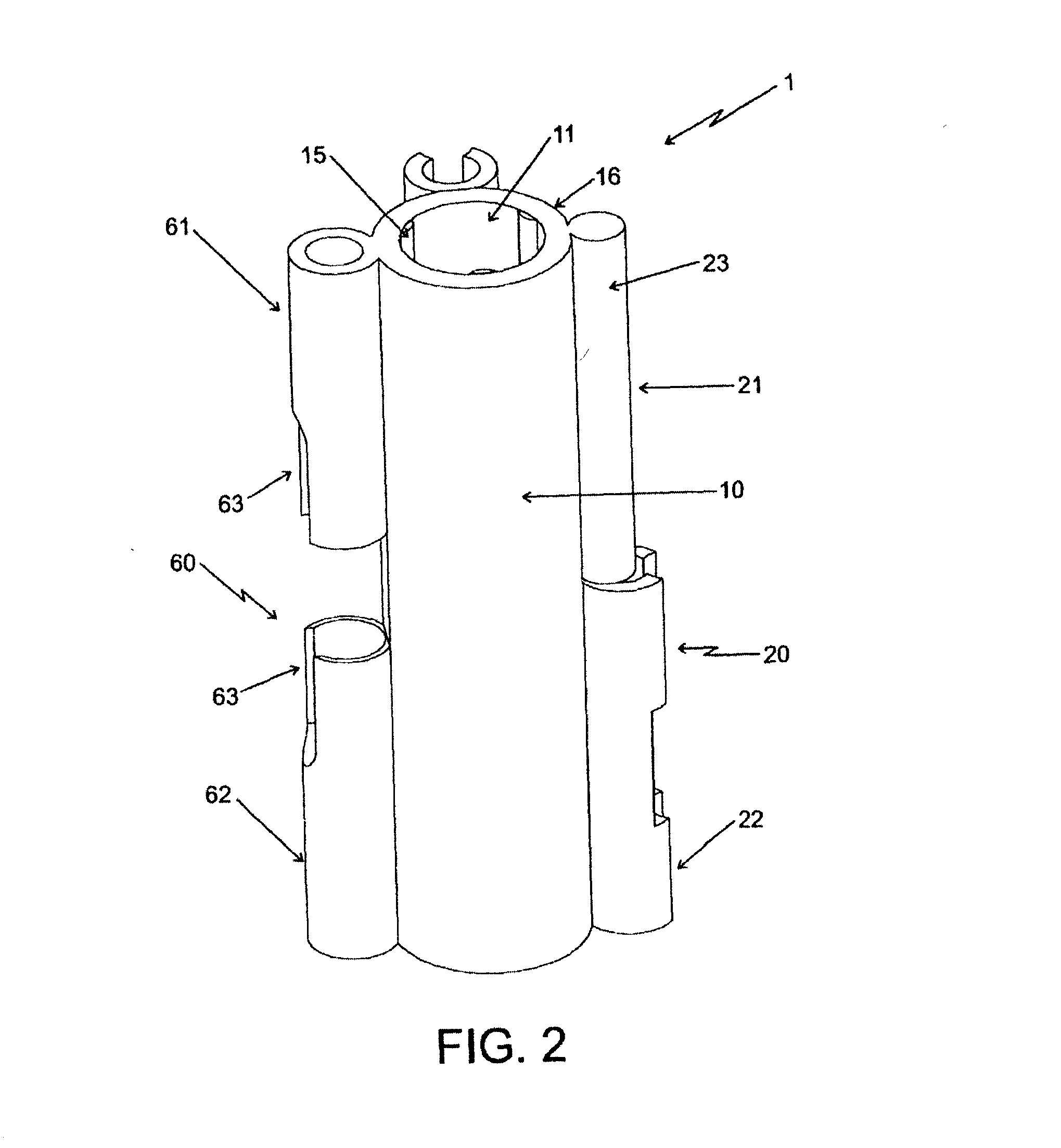
[0020] Referring to FIGS. 1 to 8, the connecting node 1 is illustrated which is formed from a cylindrical main body 10, which houses inside an upper recess 11 and a lower recess 12, separated by an intermediate wall 13, forming part of the same cylindrical main body 10. In such upper 11 and lower 12 recesses end edges extend from the cylindrical main body 10 ends towards the opposite end, being limited by intermediate wall 13, such that said upper 11 and lower 12 recesses present a depth of approximately half the total length of the main body 10 of connecting node 1, leaving such depth limited only by intermediate wall 13.

[0021] The diameter of the upper 11 and lower 12 recesses is determined such that wall thickness forming between these two recesses 11, 12 and cylindrical main body 10 is sufficiently resistant to uphold exertions to which the connecting node 1 is submitted, once structural elements 70, 71 integrating erecting structure are billeted inside such upper 11 and lower 1...


PUM


Abstract

A connecting node, manufactured on a specific plastic material is described. Said connecting node comprises a cylindrical main body lodging inside two hollow cavities with convex semicircular flanges able to provide a tight-fit between the node and the element to be connected; and wherein said connecting node further comprises three connection arrangements disposed on its right-hand side, frontal and left-hand side walls. With said arrangements a rapid and safe union between two or three connecting nodes is attained. In addition, said arrangements permit the incorporation of elements working under stress into said connecting node. Said elements connected between nodes intend to provide higher rigidity between the elements forming the structure when assembled by said connecting nodes.

Description

[0001] Within the field of the connectors or nodes for structures requiring fast and efficient assembly, there are several types of connectors manufactured from different materials, such as plastic and aluminum, among others, with the purpose of meeting assembly needs of the different elements comprising a structure, and can include from simple drill holes arranged on the connector's main body which allow bolts insertion, to fastening complex systems with screws and clamps, whereby the complexity involving the connector itself, on occasions exceed the complete structure.[0002] Normally connectors are utilized as a starting point of two or more elements of a given structure, nevertheless this perception limits connector to be part of one single structure, which does not mean it can interact with other connectors with the same characteristics being part of independent similar structures, such that a joint can be achieved of one or more independent structures by connectors or nodes.[00...

Claims


Application Information

Patent Timeline
Patent Type & Authority Applications(United States)
IPC IPC(8): F16B7/04
CPCY10T403/341F16B7/04
Inventor DE LA FUENTE, RAMON
Owner SABRITAS
Learn More