Coke drum discharge system

a discharge system and coke drum technology, applied in the field of coke drums, can solve the problems of difficult use in the production of shot coke, difficult to discharge coke, and often remain coke inside the drum

Inactive Publication Date: 2003-05-15
FOSTER WHEELER USA
View PDF18 Cites 48 Cited by
  • Summary
  • Abstract
  • Description
  • Claims
  • Application Information

AI Technical Summary

Benefits of technology

0014] This invention addresses the foregoing needs in the art by providing a discharge conduit on a coke drum, the discharge conduit having a ball valve. According to a preferred embodiment, cut coke can be removed from the coke drum past the opened ball valve down the discharge conduit, and a bottom cover of the coke drum does not need to be unheaded.

Problems solved by technology

Despite the open bottom of the drum, however, the coke often remains inside the drum until it is cut.
As a result, unheading is typically a labor intensive chore.
A further drawback of the conventional unheading process is that it is difficult to use in the production of shot coke.
As a result, the coke will often pour out of the drum as the bottom cover is being removed.
In addition, the shot coke may rest on the bottom cover, putting a large load on the bottom cover and making its controlled removal difficult.
Although Utterback mitigates the unheading problem, it also suffers from drawbacks.
First, the coke leaving the drum is at a high enough temperature that it may combust if it comes into contact with air, so additional components are required to cool the coke in an oxygen-depleted environment.
Second, the coke drum needs an outer casing to heat its walls, implicating increased cost for installation and manufacture.
As the drawbacks of Utterback and Geller indicate, the continuous process for producing coke is not always desirable.

Method used


Image

  • Coke drum discharge system

Examples


Embodiment Construction

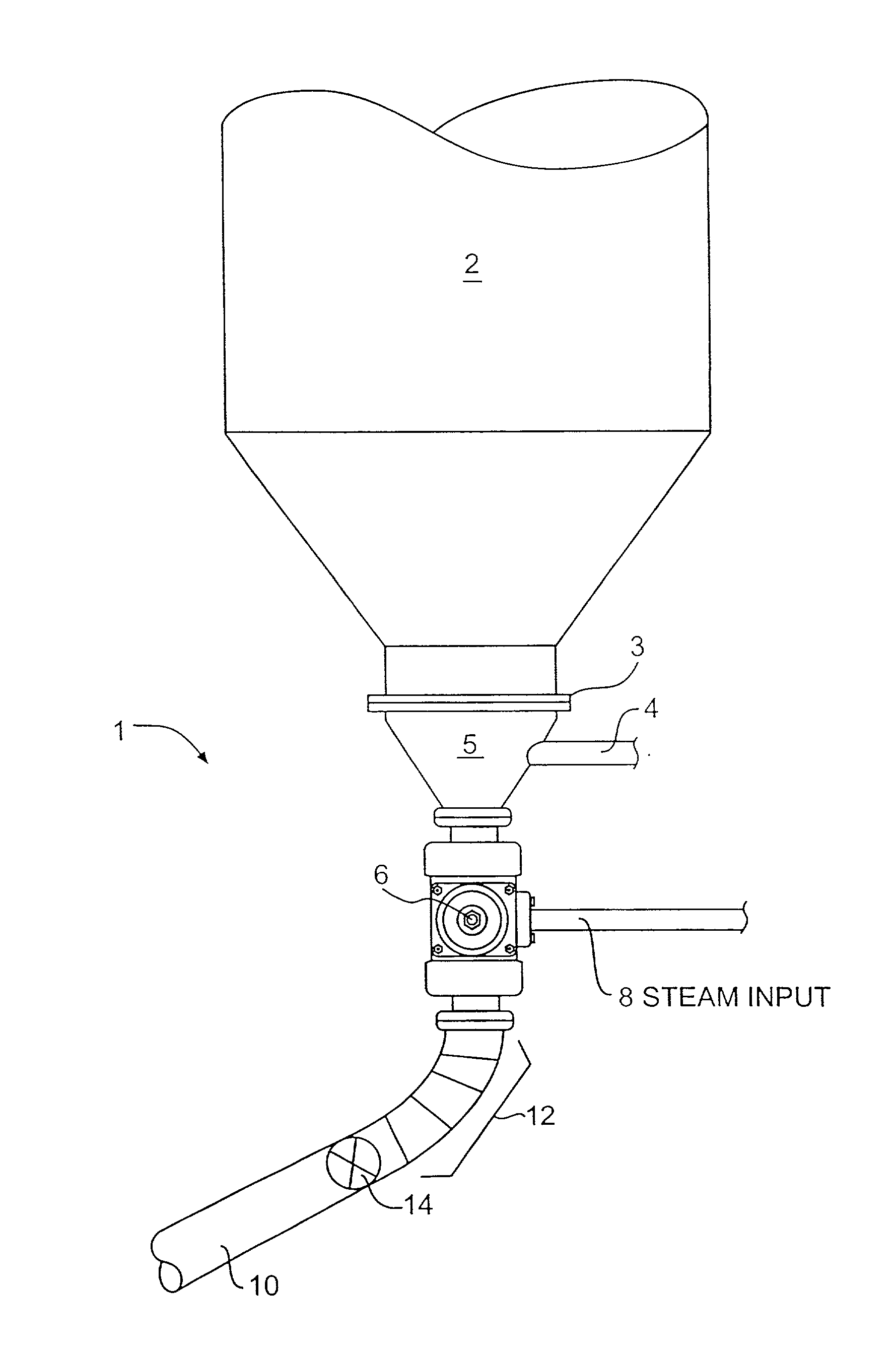
[0024] The FIGURE shows a discharge system 1 for a coke drum 2 which reduces the frequency with which a bottom flange 3 of the coke drum 2 needs to be unheaded. The discharge system 1 generally includes a ball valve 6 and a discharge conduit 10.

[0025] The discharge system 1 may be used to coke hydrocarbon substances such as petroleum, for example. Included in the system is a side conduit 4 for draining water from the coke drum 2, supplying steam or feeding a petroleum charge. The side conduit 4 is preferably connected to a funnel 5, which itself is connected to the bottom of the coke drum 2. The funnel 5 may be permanently attached to the coke drum 2, bolted on, or removably attached by hydraulic means as disclosed in U.S. Pat. No. 6,223,925 to Malsbury, for example.

[0026] Below the side conduit 4 and funnel 5 is a ball valve 6, preferably having a steam supply 8 connected to it. The ball valve 6 is preferably a conventional, double-seat, full-port ball valve. Although a ball valve ...


PUM

PropertyMeasurementUnit
pressureaaaaaaaaaa
elevated temperaturesaaaaaaaaaa
temperaturesaaaaaaaaaa

Abstract

An apparatus including a coke drum for coking hydrocarbon substances, a valve disposed near the bottom of the coke drum, and a discharge conduit for removing coke from the coke drum, wherein the discharge conduit is connected to the valve such that when the valve is open, the coke may be removed via the discharge conduit.

Description

[0001] This application claims benefit of provisional application No. 60 / 331,156, filed Nov. 9, 2001.BACKGROUND OF THE INVENTION[0002] 1. Field of the Invention[0003] This invention relates to a coke drum, and more particularly, to a discharge system for a coke drum.[0004] 2. Background of the Invention[0005] In a conventional delayed coking process, petroleum residues are fed at elevated temperatures to a large steel vessel called a coke drum, where the residues are thermally cracked and formed into coke. When the coke drum has filled with coke, the drum is injected with steam and cooled with water. Subsequently, top and bottom covers of the drum are removed in a process called unheading. Despite the open bottom of the drum, however, the coke often remains inside the drum until it is cut. When cut, the coke falls out of the open bottom of the drum down a chute or other conduit, so that it may be transported and further processed.[0006] As discussed above, the conventional coking pr...

Claims


Application Information

Patent Timeline
Patent Type & Authority Applications(United States)
IPC IPC(8): C10B57/04B01J8/00C10B33/00C10B33/12C10B55/00
CPCB01J8/003B01J2208/00761C10B55/00C10B33/12C10B33/00
Inventor MALSBURY, ALLEN S.
Owner FOSTER WHEELER USA
Why Eureka
Try Eureka